
AVR robots

The AVRcam hardware has undergone several revisions since its inception in April 2004. The hardware design is straightforward, with the Atmel AVR Mega8 serving as the primary processing unit. The Omnivision OV6620 CMOS image sensor connects directly to the Mega8 to access essential camera signals such as pixel clock, horizontal and vertical sync, and data buses. A recent addition to the hardware is the AVR Tiny12, an 8-pin microcontroller that configures the OV6620 to output its clock signal on one of its pins. This clock signal is utilized by the Mega8 as its clock source, ensuring synchronization for processing the real-time stream of pixel data.
The AVRcam embedded software is structured into various classes that implement the necessary functionalities. The core of the software revolves around the Camera Interface class, which manages the interaction with the OV6620. The Frame Manager utilizes data from the Camera Interface to perform frame-level calculations and decisions. A User-Interface Manager operates alongside the Frame Manager, processing incoming commands and generating the required outgoing serial packets. An event-dispatching executive oversees the management of events generated within the system. The AVRcam class diagram illustrates these components.
The AVRcam software is primarily written in C, utilizing the free AVR-GCC C compiler, with critical camera interfacing routines implemented in Assembly to ensure cycle efficiency. These routines are essential for maintaining the system's performance at 30 frames per second. The AVRcamVIEW PC software provides a user-friendly interface for testing and calibrating the AVRcam. This application, compatible with both Windows and Linux, communicates with the AVRcam through a standard 9-pin serial port. Users can capture full-resolution snapshots (176 x 144 pixels) and analyze the colors present in the camera's field of view. They can create a color map by selecting colors from the image and adding them to the map. Once the color map is configured, it can be sent to the AVRcam, enabling it to begin tracking. When tracking is activated, the AVRcamVIEW application displays the currently tracked objects, including color and bounding box information, with updates occurring at the full frame rate.
The AVRcam system exemplifies an effective integration of hardware and software for real-time image processing, making it a valuable tool for hobbyists and developers in various applications.The line is purposefully not straight, to see how it would do with zig-zags and splits, as are normal for the Chibots advanced line-following contest. The AVRcam is a small, real-time image processing engine capable of tracking colorful objects. The system was specifically designed to provide the everyday-hobbyist with a vision system that can be easily
added to their projects (robot, security, monitoring, etc). Based on the Atmel AVR mega8 microcontroller and the Omnivision OV6620 CMOS image sensor, the AVRcam has the following capabilities: In addition, the AVRcam is supported for demonstration and calibration by a PC application called AVRcamVIEW. This software provides the following capabilities: Adjust the precision of each tracked color (i. e. provide a range of acceptable R-G-B values for each color), allowing the user to adjust the Color Map to the available lighting conditions The AVRcam hardware has evolved several times since the project began in April of 2004.
As can be seen in Figure 1, the hardware is very straight forward. An Atmel AVR mega8 provides the main processing needed by the system. The Omnivision OV6620 CMOS image sensor is connected directly to the mega8 to access important camera signals (pixel clock, horizontal and vertical sync, and, of course, the data busses). A new addition to the hardware is the AVR Tiny12, which is a small 8-pin microcontroller. This micro was added to the system to configure the OV6620 to output its clock signal on one of its pins.
This clock signal is then used by the mega8 as its clock source. Having a single clock source shared between the mega8 and the OV6620 provides the necessary synchronization to allow the system to process the real-time stream of pixel data. The AVRcam embedded software is divided up into a set of classes that implement the functionality required.
The main crux of the software revolves around the Camera Interface class, which implements the core functionality of interfacing to the OV6620. The Frame Manager utilizes the data gathered by the Camera Interface class to make frame-level calculations and decisions.
A User-Interface Manager sits as a peer to the Frame Manager, and is responsible for processing incoming commands and generating the needed outgoing serial packets. Finally, a simple event-dispatching executive sits at the top of the system to facilitate the handling of the events that get generated in the system.
The AVRcam class diagram is shown in Figure 2. The AVRcam software was written almost entirely in C, using the free AVR-GCC C compiler. Several of the critical camera interfacing routines were written in Assembly in order to explicitly ensure the number of cycles that would be used for the routines. These routines provide the core capability of the system, and what allow the system to keep up when running at 30 frames/sec.
The AVRcamVIEW PC software provides a simple way to test and calibrate the AVRcam. This application runs on a PC (either Windows or Linux), and communicates with the AVRcam through the standard 9-pin serial port of the PC. The AVRcamVIEW software allows the user to take full resolution snapshots (176 x 144 pixels) and analyze them to determine the colors that are present in the camera`s field of view.
The user can then build a color map, to indicate which colors the AVRcam should track, by selecting the colors in the image and adding them to the color map. Once all the colors have been selected, this color map can then be sent down to the AVRcam to configure it.
The AVRcam is then ready to begin tracking, which can be enabled by the AVRcamVIEW control panel. When tracking is enabled, the AVRcamVIEW application will display the currently tracked objects (both color and bounding box info). The display is updated at the full frame rate 🔗 External reference
Related Circuits
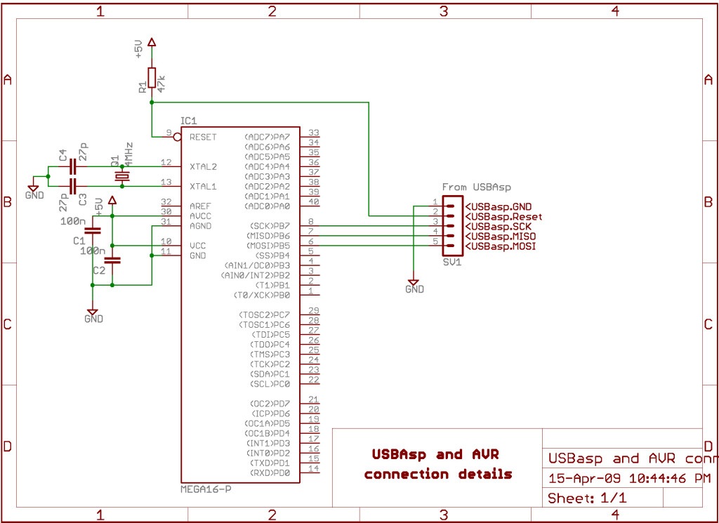
An Atmega32A chip has been programmed using a USBasp programmer. While it is possible to change the fuses and write the program, verification fails. The chip can be erased, and the fuses can be altered, but the issue lies...
An EEPROM is a type of non-volatile memory, which means it is used for permanently storing digital data without any power supply. EEPROM stands for Electrically Erasable Programmable Read-Only Memory. The advantage of this type of ROM is that...

The schematic includes programmable AVRs. For other members of the AVR family or additional programmable ICs compatible with Ponyprog, there is a J1 connector (CON10) that facilitates hardware expansion of the programmer. Additional information about compatible ICs can be...
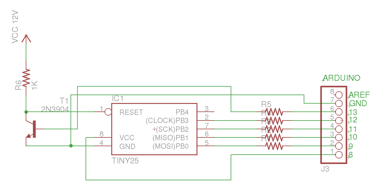
This Arduino sketch is designed to recover ATtiny microcontrollers that have become non-functional due to incorrect fuse settings. It achieves this by placing the affected ATtiny into high-voltage serial programming mode and rewriting the fuses to safe values. The...

Inspired by the work of Nanode and a recent Instructable, an AVR-based Ethernet board has been developed that can be programmed and utilized similarly to an Arduino. This straightforward design is based on the ATMega microcontroller and Microchip's ENC28J60...
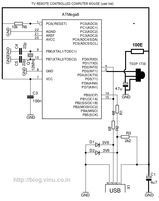
While lying in bed and watching movies on a laptop, the idea arose that having a remote control would simplify the tasks of pausing, playing, fast forwarding, rewinding, adjusting volume, and playing the next track without needing to approach...