
ba1404 fm stereo modulator

The BA1404 FM stereo modulator is designed for applications where a compact and efficient stereo transmission is needed. The circuit is suitable for hobbyists and professionals looking to create a low-power FM transmitter. The architecture of the BA1404 includes a stereo modulator section that combines left and right audio channels into composite signals, which are essential for stereo broadcasting.
The operation begins with the audio input, where the left (L) and right (R) audio signals are fed into the stereo modulator. This modulator processes the signals to create the composite output, which includes the main signal (L+R) and the difference signal (L-R) along with the pilot tone (19 kHz). The pilot tone is crucial for stereo decoding on the receiving end, ensuring that FM receivers can accurately reproduce the stereo sound.
The FM modulator then takes these composite signals and modulates them onto a carrier frequency within the FM broadcast band. The carrier frequency is determined by the external components and the configuration of the circuit. The RF amplifier boosts the modulated signal to ensure it can be transmitted over a considerable distance without significant loss of quality.
To implement this circuit, a 38 kHz crystal oscillator is employed, which serves as a stable frequency reference for the modulation process. This oscillator is critical for generating the pilot tone and ensuring the integrity of the stereo signals. The choice of external components, such as resistors, capacitors, and the antenna, will influence the overall performance and range of the transmitter.
In summary, the BA1404 FM stereo modulator is a versatile IC that simplifies the design of FM stereo transmitters. It integrates multiple functions into a single package, making it an ideal choice for creating efficient and effective FM broadcasting solutions. With the appropriate external components and careful circuit design, high-quality stereo audio can be transmitted within the FM band, catering to various applications in audio broadcasting.Using BA1404 can be designed a very simple and useful fm stereo modulator electronic project. This BA1404 fm stereo modulator device works in FM broadcast band ( 75- 108MHz) and require few external common components. The BA1404 fm stereo modulator Ic contains all parts needed to design an simple high efficiency stereo transmitter circuit.
This IC contains a stereo modulator that creates stereo composites signals, an FM modulator that creates FM signals and a RF amplifier. The fm stereo transmitter develops composite signals made up of a main(L+R) signal and sub(L-R) signal and a pilot (19KHz) signal using a 38KHz crystal oscillators.
🔗 External reference
Related Circuits

Using a Thomson TEA2025, this stereo amplifier delivers 1 W per channel into a 4-ohm load with a 9-V supply. The input sensitivity is 25 mV peak-to-peak for full output. It is important to ensure that pins 4, 5,...
The function of the sound level display circuit is to enhance the appearance of an amplifier circuit or a radio player. It provides an impressive visual representation of audio levels. The sound level display circuit serves as a visual indicator...
This project is straightforward to construct and will transmit high-quality sound within the FM band (88-108 MHz). An important component is that the... This project involves the design and construction of a simple FM transmitter capable of broadcasting audio signals...
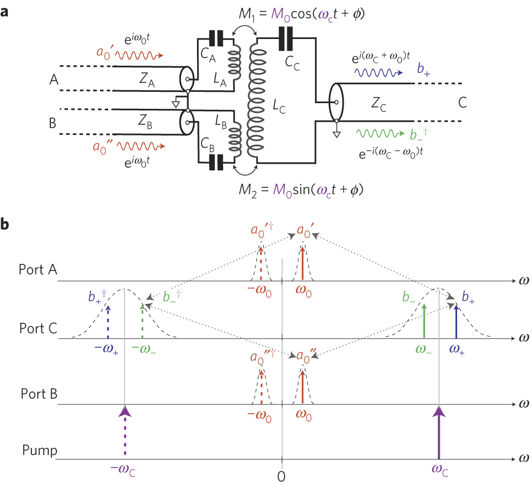
The circuit schematic of the UDC consists solely of dispersive components. Two low-frequency series LC resonators, with equal inductances (LA=LB) and capacitances (CA=CB), are connected to two input semi-infinite transmission lines, designated as A and B. These resonators are...
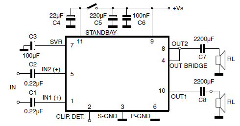
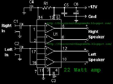
The car radio application utilizes a Class AB Audio Power Amplifier, typically featuring the TDA7360 IC. This amplifier provides 22W output in either bridge or stereo configuration and includes several beneficial features such as a minimal requirement for external...
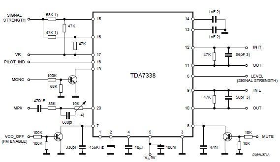
The pilot detector output is configured as an open collector output, requiring an external pull-up resistor. To set the decoder to "MONO," Pin 19 must be clamped to a voltage below 0.8V. The open collector output configuration allows for multiple...