
Stereo VU Meter Circuit LM3915 IC

The sound level display circuit serves as a visual indicator of audio signal levels, improving the aesthetic appeal and functionality of audio devices such as amplifiers and radio players. Typically, this circuit utilizes light-emitting diodes (LEDs) or liquid crystal displays (LCDs) to represent the amplitude of the audio signal in real-time.
The circuit usually consists of several key components: an audio input stage, a signal processing unit, and the display unit. The audio input stage often comprises a microphone or line-level input to capture the audio signal. This signal is then filtered and amplified to ensure that it is suitable for further processing.
The signal processing unit typically includes an analog-to-digital converter (ADC) if the display is digital, or it may utilize analog components such as rectifiers and peak detectors for analog displays. This unit processes the audio signal to extract relevant information about its amplitude, which is then used to control the display.
In the display unit, LEDs or LCDs light up in response to the processed audio signal levels, providing a visual cue that corresponds to the loudness of the sound being played. The design may include multiple LEDs arranged in a bar graph format, where each LED represents a specific range of audio levels, or a single multi-segment display that indicates the current level of the audio signal.
The circuit can be powered by a standard DC power supply, and careful consideration should be given to the power requirements of each component to ensure reliable operation. Additional features such as adjustable sensitivity or peak hold functions can also be implemented to enhance the circuit's functionality.
Overall, the sound level display circuit not only enriches the user experience by providing a visual representation of audio levels but also improves the overall design and usability of audio equipment.The function of sound level displayer circuit to improve the out look of your amplifier circuit or your Radio player. Actually this gives an unbelievable .. 🔗 External reference
Related Circuits
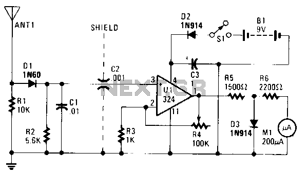
The untuned, yet amplified Frequency Selective Measurement (FSM) circuit can detect signals ranging from 3 to 148 MHz and is remarkably resistant to overload, ensuring that the meter pointer does not reach its maximum. The core component of this...
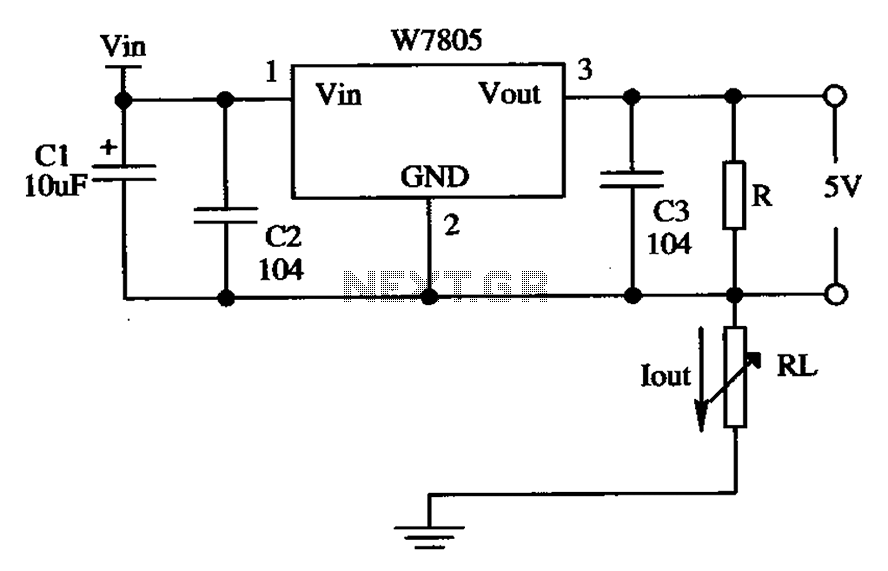
The circuit is composed of a W7805 positive current source application integration circuit that includes a voltage regulator. The W7805 regulator operates in suspension. A resistor is placed between its output terminal and the common terminal, forming a constant...
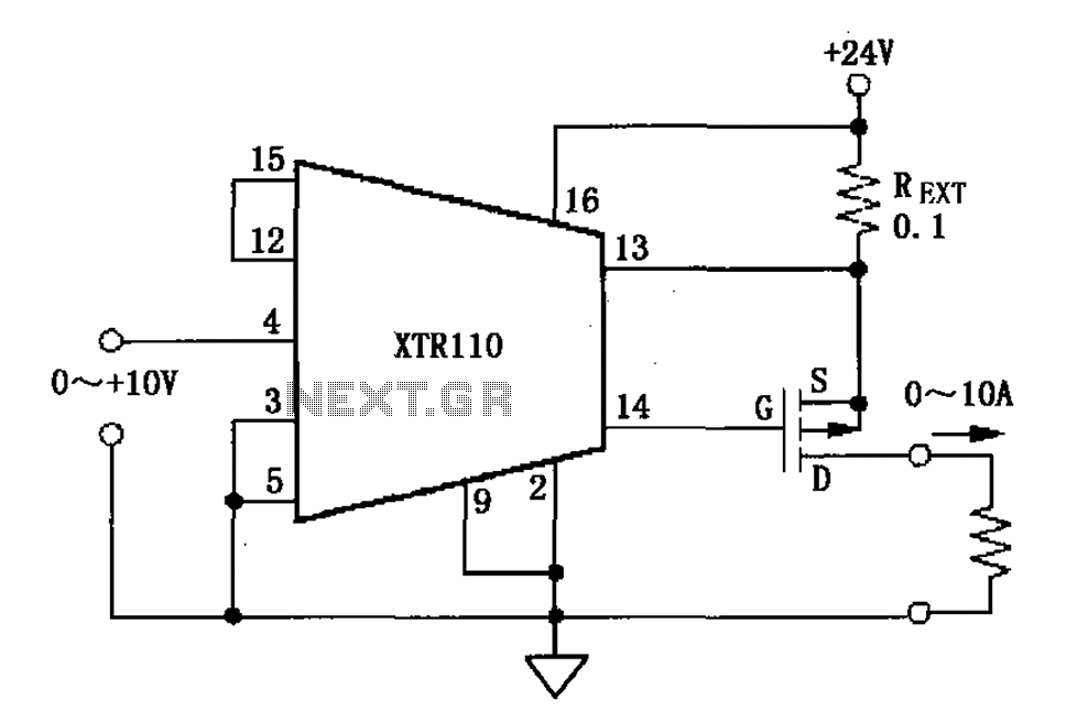
When the output current exceeds 40mA, the XTR110 requires the use of an external resistor (REXT) instead of the internal 50-ohm resistor (R9). REXT should be connected between pin 13 and pin 1. The value of REXT is determined...

The robot requires a method for detecting obstacles (or other robots) without making physical contact. This capability allows the robot to determine whether to avoid or confront and investigate the obstacle based on its programming. This document outlines the...
The following circuit illustrates a Water Level Detector Circuit Diagram. This circuit is based on the PIC12F683 microcontroller. Features include the ability of the PIC microcontroller to enter a sleep mode. The Water Level Detector Circuit utilizing the PIC12F683 microcontroller...
This automatic light dimmer circuit enables the gradual control of a lighting system, allowing it to turn on or off slowly. The operation of the circuit is as follows: when switch S1 is closed, capacitor C1 charges slowly. Once...