
Background music decoder

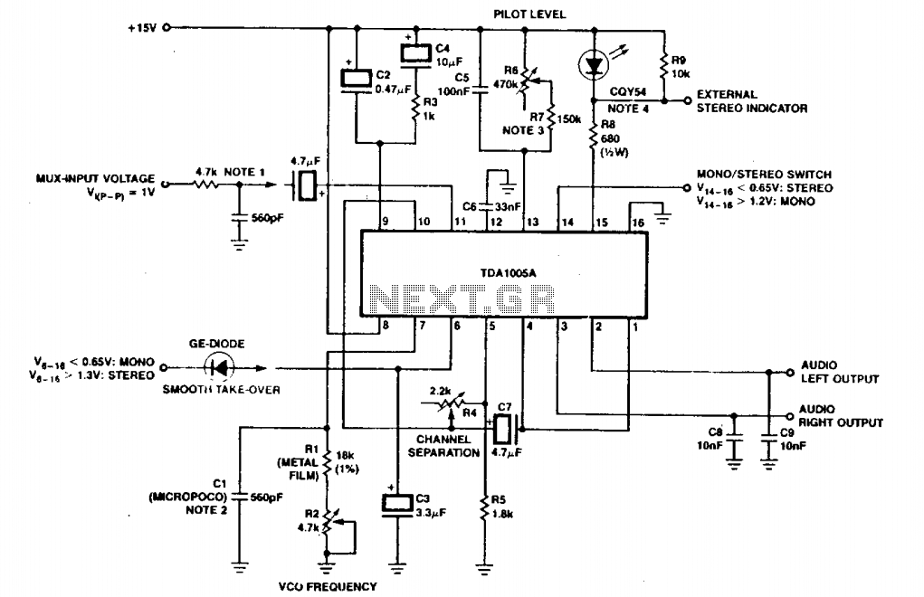
In this circuit setup, the resistive voltage divider plays a critical role in establishing a stable bias voltage for the input pins, ensuring that the signal levels are appropriate for processing. The two-stage high-pass filter is crucial in preventing low-frequency signals from saturating the input stage while also allowing higher frequency signals to pass through with minimal attenuation. This filter is typically composed of capacitors and resistors configured to form a passband that effectively blocks frequencies below a certain threshold.
The Phase-Locked Loop (PLL) is an essential component in this circuit, allowing for the locking onto the desired frequency of 67 kHz. The use of a 5000-ohm potentiometer facilitates fine-tuning of the PLL, enhancing the circuit's ability to track the input signal accurately. The automatic seeking capability of the PLL ensures that even with slight variations in frequency, the circuit maintains synchronization with the incoming FM signal.
The subsequent three-stage low-pass filter connected to Pin 7 is designed to mitigate high-frequency noise that can interfere with the clarity of the demodulated audio signal. This filter typically consists of multiple RC networks that progressively reduce the amplitude of frequencies above the desired audio range, effectively providing a cleaner output for further processing or amplification.
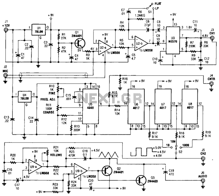
The absence of a capacitor at Pin 7 indicates a simplified first-order filtering approach, which may be sufficient for certain applications, particularly where space or component count is a concern. The output signal level of approximately 50 mV, combined with a frequency response extending to 7 kHz, suggests that the circuit is well-suited for audio applications where fidelity and noise reduction are important. This design offers a balance between performance and complexity, making it a viable solution for FM demodulation tasks in various electronic systems.A resistive voltage divider is used to establish a bias voltage for the input (Pins 2 and 3). The demodulated (multiplex) FM signal is fed to the input through a two-stage high-pass filter, both to effect capacitive coupling and to attenuate the strong signal of the regular channel. A total signal amplitude, between 80 mV and 300 mV, is required at the input. Its source should have an impedance of less than 10,000 ohm. The Phase-Locked Loop is tuned to 67 kHz with a 5000 ohm potentiometer, only approximate tuning is required since the loop will seek the signal.
The demodulated output (Pin 7) passes through a three-stage low-pass filter to provide de-emphasis and attenuate the high-frequency noise which often accompanies SCA transmission. Note that no capacitor is provided directly at Pin 7; thus, the circuit is operating as a first-order loop. The demodulated output signal is in the order of 50 mV and the frequency response extends to 7 kHz.
Related Circuits
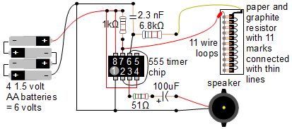
A simple music instrument/keyboard is created using a 555 timer chip circuit, a piece of paper, and a pencil. The project includes a more advanced automatic music player that utilizes a playing head and a long sheet of paper...
The STK672-050 is a unipolar constant-current chopper-type externally-excited 4-phase stepping motor driver hybrid integrated circuit (IC) that utilizes MOSFET power devices. It features a built-in microstep operation-supported 4-phase distributed controller, enabling the realization of a high torque, low vibration,...
There have been numerous inquiries regarding this project, primarily due to issues with the source code provided at the end of the author's notes. This problem has been widely reported online, and similar compilation errors have been encountered. It...
One section of the precision audio frequency generator utilizes an electret microphone element to capture audio from the piano. The captured signal is processed and transmitted to one channel of a dual-trace oscilloscope. The other section of the circuit...
500 Series immersion temperature probe, NTC, 100,000 Ohm, ±1.5 °C [±2.7 °F] tolerance, 10 °C to 260 °C [50 °F to 500 °F] accuracy, stainless steel, bullet housing, flying leads (two), 26 gauge Teflon insulation, 4,267 mm [168 in]. The...
The circuit depicted includes an RC filter (Figure T). The micropico capacitor has a temperature coefficient of 125 x 10^-6 at 60 x 10^-6°C. In simplified circuits, a fixed resistor, such as 620kΩ, can be utilized to ensure a...