
Balanced Line Driver & Receiver

This project involves the conversion of unbalanced audio signals to balanced signals, which is beneficial for reducing noise and interference over long cable runs. The circuit can be implemented using operational amplifiers (op-amps) configured to create a differential signal from the unbalanced input. The unbalanced signal, typically carried over an RCA connector, is fed into an op-amp circuit where it is transformed into a balanced output suitable for XLR connectors.
The balanced line consists of two conductors carrying the same audio signal but with opposite polarity. This configuration allows the receiving end to reject any noise that may have been picked up along the cable, as the noise will likely affect both lines equally and can be canceled out. The circuit can also include a phantom power feature, which allows the remote device to be powered directly through the audio cables. This is achieved by injecting a low voltage DC signal, typically around 48V, onto the balanced lines, which can then be extracted by the microphone or other low-current devices at the receiving end.
For the implementation, the circuit design will include the following components:
1. Two op-amps for differential amplification.
2. Resistors to set the gain and balance the circuit.
3. Capacitors for filtering and stability.
4. A power supply circuit to provide the necessary voltage for the op-amps and phantom power.
The design should ensure that the op-amps are configured correctly to minimize distortion and maintain audio fidelity. The use of high-quality components is recommended to achieve optimal performance. Additionally, proper grounding techniques should be employed to further reduce noise and interference.
In conclusion, this project provides a practical solution for converting unbalanced audio signals to balanced lines, with the added capability of phantom powering, making it an excellent experiment for audio enthusiasts and professionals alike.With this simple project, you can have balanced lines too, simply adapting the unbalanced inputs and outputs of your hi-fi gear to become balanced, and then back to unbalanced at the other end. You can even be extra cunning, and power the remote converter from the cables carrying the signal. Professionally, this is called "Phantom Feed", and is used to power microphones and other low current equipment.
The version I have shown is actually a differential feed. Whilst not as good as a true 48V phantom powering circuit, it does work, and makes an interesting experiment (if nothing else). Before we start, a brief description of the standard (unbalanced) and balanced line is in order. An unbalanced line is the type you have on the hi-fi, typically using an RCA connector, and feeding the signal through a coaxial cable. The inner cable carrie 🔗 External reference
Related Circuits
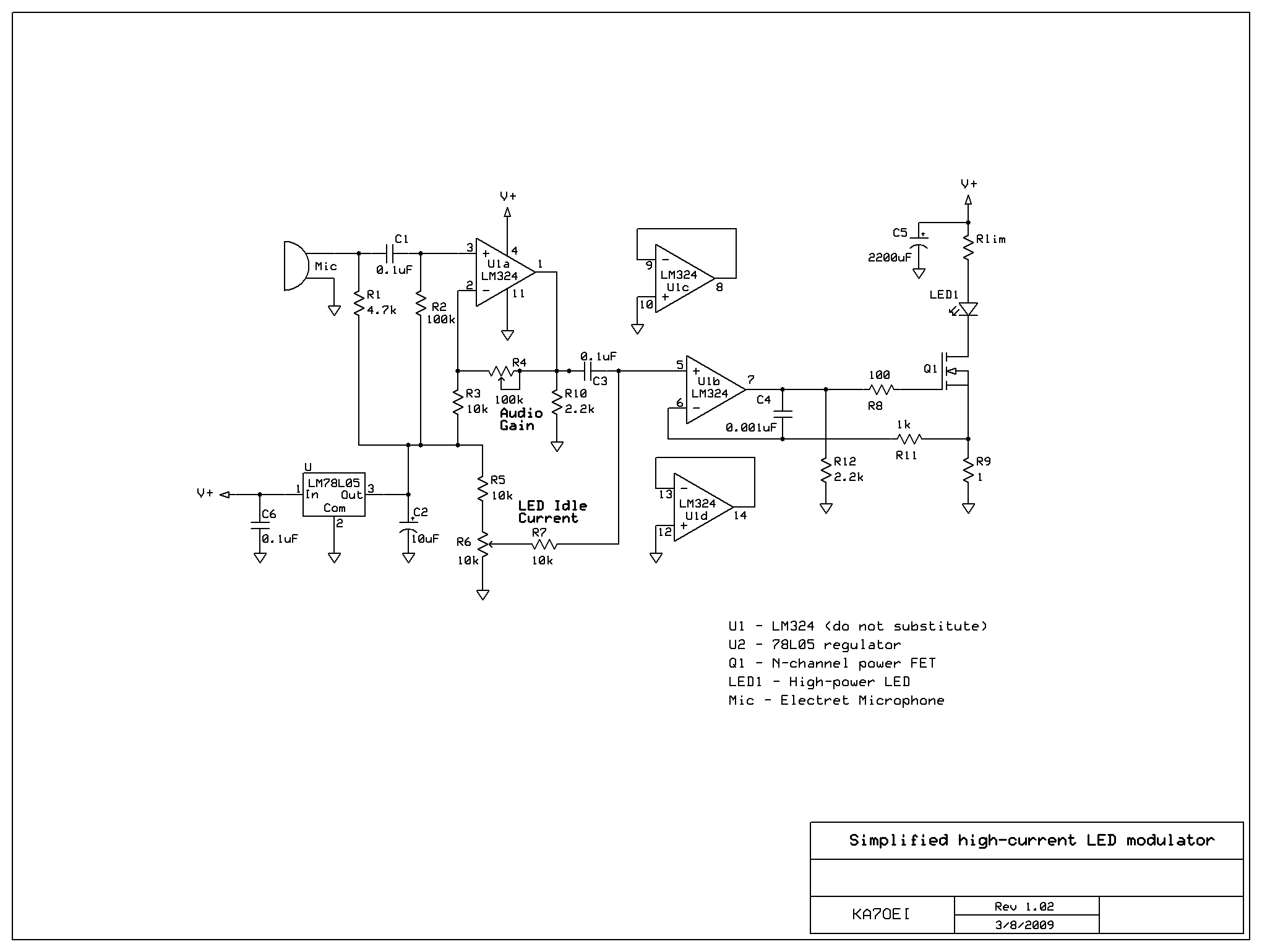
After constructing a Pulse Width Modulator for high-power LEDs, another LED modulator was developed for an optical transceiver. This project utilized a different approach, focusing solely on linear techniques for audio modulation. Similar to the PWM circuit, this circuit...
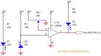
This circuit diagram illustrates a Line Follower / Line Tracker robot. The circuit is derived from tutorial documentation, which is available for download at the conclusion of this article. The line follower robot utilizes eight proximity sensor modules. Each...
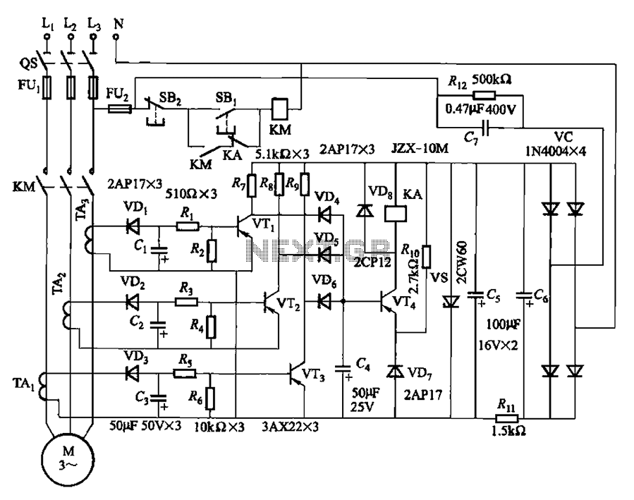
The current detection signal is obtained from three current transformers after rectification and filtering, resulting in three DC voltage outputs. These voltages are applied to transistors VT1, VT2, and VTa between the base and emitter. The signal is amplified...
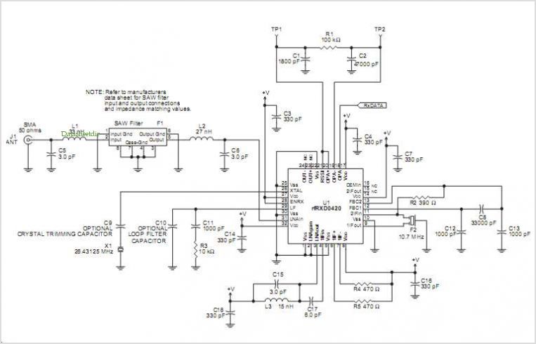
The RFRXD0420 and RFRXD0920 are low-cost, compact, single-frequency short-range radio receivers that require only a minimal number of external components for a complete receiver system. The RFRXD0420 operates within the frequency range of 300 MHz to 450 MHz, while...
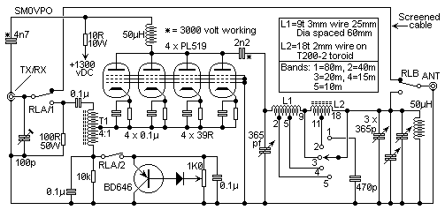
This is the circuit of a 500 watt linear amplifier, based upon a design by Frits Geerligs, PA0FRI, who has his own homepage at http://home.planet.nl/~fhvgeerligs. The circuit uses four PL519 TV line output valves in a very simple circuit...
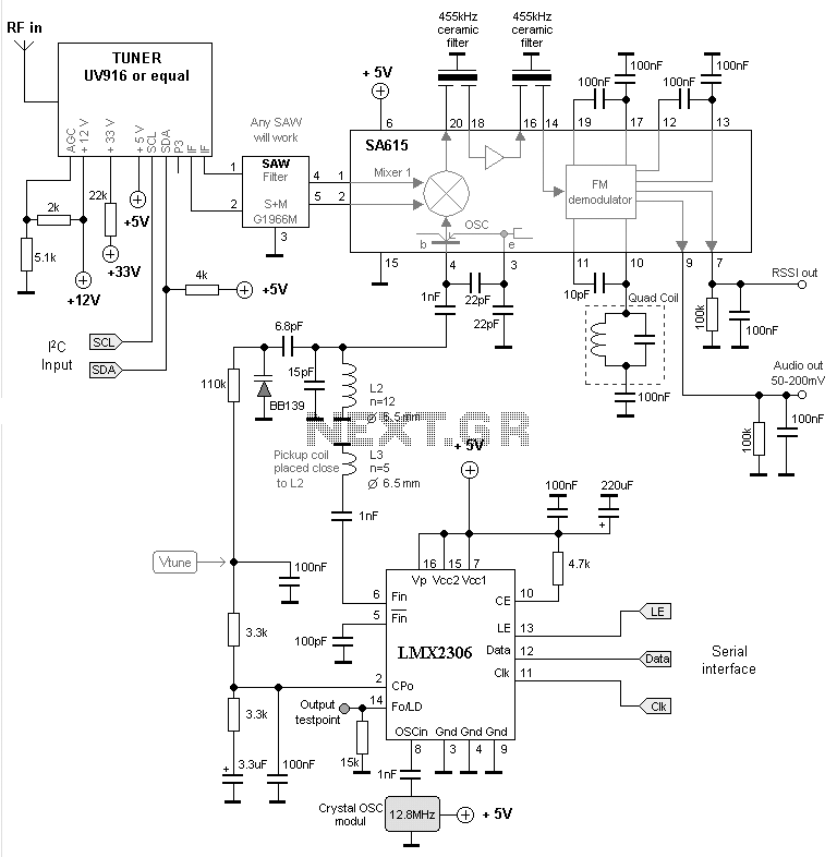
The MC13136 circuit is not easy to find so I have replaced it with a new receiver circuit called SA615. This is a basic FM receiver with very good performance and sensitivity. In my super receiver I used a...