
LED linear modulator

The LED modulator circuit described employs a precision current sink to ensure consistent current regulation, which is critical for maintaining the desired brightness levels in high-power LED applications. The linear modulation technique allows for more straightforward control of the LED's light output, making it suitable for applications where audio modulation is required. This approach contrasts with PWM methods, which can introduce switching noise and ripple in the output.
The tone generator included in the design serves as a useful tool for testing and calibration. By generating specific audio frequencies, it enables the user to verify the modulation characteristics of the LED in real-time. This feature is particularly beneficial when aligning the optical transceiver, ensuring that the LED operates within the specified parameters for optimal performance.
In practical terms, the circuit can be divided into two primary sections: the current regulation module and the tone generation module. The current regulation module utilizes operational amplifiers and transistor configurations to create a stable current sink, allowing for precise control of the LED's brightness. The tone generator, likely implemented using a microcontroller or a dedicated audio IC, produces a range of frequencies that can be adjusted as needed for testing purposes.
Overall, this LED modulator design emphasizes reliability and simplicity, making it an effective solution for applications requiring precise control over LED output in optical communication systems. The linear modulation technique, combined with the added tone generation capability, enhances the functionality and usability of the circuit in real-world scenarios.After constructing the Pulse Width Modulator for High Power LEDs I needed to build another LED modulator for another optical transceiver. For this project I decided to take a different approach and use solely linear techniques for the audio modulation.
Like the PWM circuit, this circuit also uses the "precision current sink" to regulate set the LE D current but in addition to the linear modulator, a tone generator - based on the same source code as in the PWM circuit - was added to facilitate testing and aiming. In order to linearly modulate the intensity of an LED it is necessary to vary the amount of current flowing through the device rather than the voltage across it.
It is fortunate that the luminous output of an LED is linearly proportional to the current flowing through it: At higher currents, the "current versus light output" curve "flattens" a little bit, but this results on only a very small amount (a few percent at most - see the sidebar below) of distortion and is unnoticeable in voice communications. 🔗 External reference
Related Circuits

The circuit presented is an integrated circuit (IC) controlled emergency light. Its key features include automatic activation of the light during mains failure and a battery charger equipped with overcharge protection. In the absence of mains power, relay RL2...
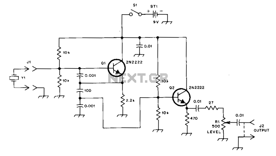
This general-purpose signal source is highly effective for signal-tracing applications. The output level is adjustable, exceeding 1 Vrms into a 50 Ω load. It is compatible with nearly any crystal in the 1 to 15 MHz frequency range. Q1...
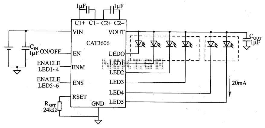
CAT3606 is a high-efficiency white LED driver. This adjustable charge pump is suitable for general-purpose, large-panel, flicker-free white LED backlighting and dual-display systems. The CAT3606 inductor boost circuit can replace conventional high-brightness backlighting requirements, thereby simplifying system design. It...
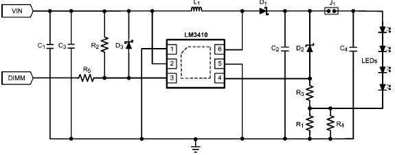
The LM3410 constant current LED driver is a monolithic integrated circuit that enables the design of high-efficiency, low-cost lighting solutions using a minimal number of electronic components. It employs current-mode control and internal compensation to ensure optimal performance across...
Simple pathway lighting that provides illumination for the path at night. Extension for the solar garden light. The toroid is bifilar wound. The described circuit involves a solar-powered pathway lighting system designed to illuminate walkways during nighttime. This system...

This project I made for my little daughter. It is 24 channel light illumination. The schematic is very simple 24 LEDs, 1 MCU and some additional components. The main principle is dynamic indication, which is usually implemented for control...