
Balanced mixer circuit consisting of two dual-gate field effect transistor formed

The balanced mixer circuit employs two dual-gate field effect transistors to achieve effective mixing of signals. The RF signal is first fed into the circuit through an input transformer (T1), which ensures proper impedance matching and signal integrity. Each FET has two gates, allowing for improved control over the mixing process and enhanced linearity.
The local oscillation signal, which is crucial for the mixing operation, is coupled to the gates of the FETs using a second transformer (T2). This coupling ensures that the oscillation signal is appropriately phase-aligned with the RF input, facilitating optimal signal processing. The advantage of using dual-gate FETs in this configuration is the ability to handle higher frequency signals while minimizing distortion and improving overall performance.
The drain outputs of the FETs, labeled as VT1 and VT2, are connected to an intermediate frequency transformer (IFT). This transformer is responsible for selecting and amplifying the desired intermediate frequency signal, which in this design is set to 10.7 MHz. The choice of this frequency is common in various RF applications, particularly in FM demodulation and communications systems.
The balanced mixer configuration enhances signal isolation and minimizes interference, making it suitable for applications where high fidelity and low noise are critical. The circuit's design allows for efficient signal processing, ensuring that the resulting output maintains the integrity of the original RF signal while providing the necessary frequency conversion. Balanced mixer circuit is shown by the two dual-gate field effect transistor. RF signal by the input signal transformer Tl effect transistors coupled to the gate of the two, th e local oscillation signal by the coupling transformer Tz added two additional field effect transistor gates, two field-effect transistors (VT1, VT2) drain pole outputs the intermediate frequency transformer din (IFT), select the 10.7 MHz IF signal output.
Related Circuits
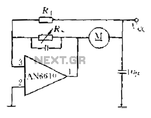
AN6610 Application Circuit operates as follows: When the supply voltage (Vcc) changes due to mechanical load variations, it can affect the motor speed. The motor speed is proportional to the back electromotive force (EMF). Consequently, the voltage across the...
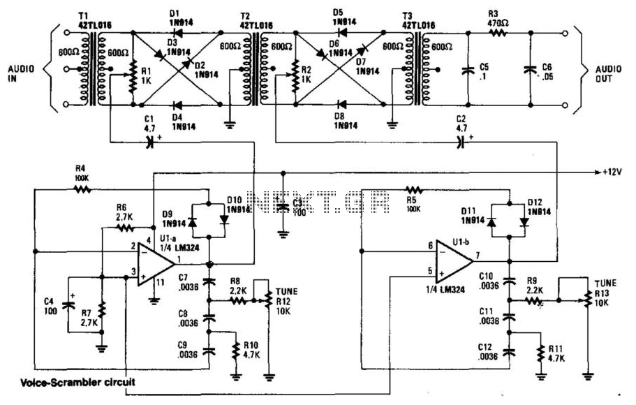
This circuit employs two balanced modulators to generate a Double Sideband (DSB) signal, followed by the reinsertion of a carrier frequency that differs from the original. This alteration leads to distortion of the input signal. While a voice signal...
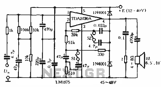
This circuit features bass boost compensation for a practical power amplifier. It is important to adhere to the specified parameters of the amplifier circuit elements. When switches S1 and S2 are disconnected, the bass boost function can be set...
White LEDs have a rated current at a voltage drop of about 3.3 to 3.4 V. It is ideal to be powered from the battery voltage which is slightly larger. Then there is the best energy used. In this...
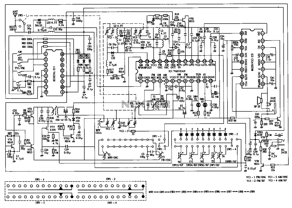
The circuit diagram for the Desheng 119 700 type FM, TV sound, medium wave, and short wave high sensitivity L2-band stereo radio is presented below. The Desheng 119 700 type radio circuit is designed to receive various frequency bands including...
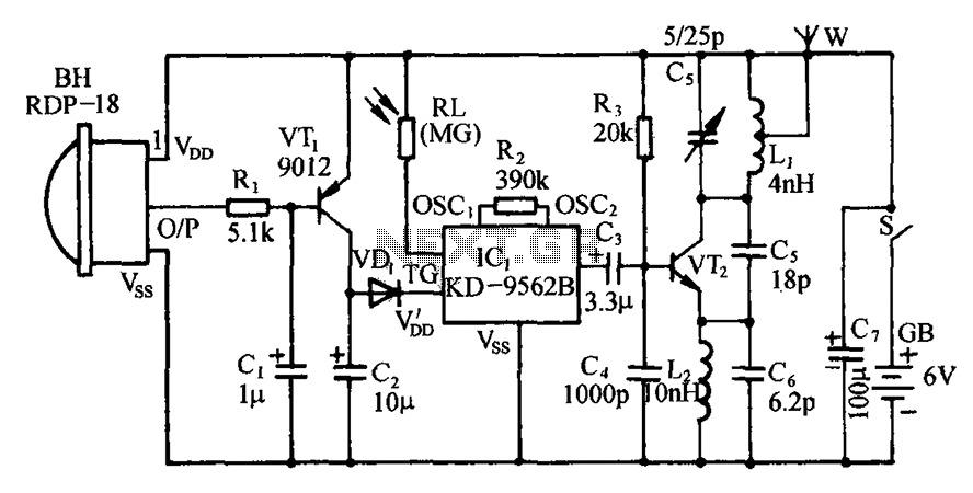
The circuit includes an infrared sensor head, electronic switches, an audible audio circuit, and an FM radio circuit. It is designed for installation in banks, treasuries, and other areas requiring supervision during evening hours in lieu of staff presence....