
Voice Scrambler/Disguiser Circuit

This circuit design utilizes two balanced modulators to create a Double Sideband (DSB) amplitude modulation signal. The DSB signal is characterized by its two sidebands, which carry the same information as the original input signal but without the carrier frequency. The reinsertion of a carrier at a different frequency introduces a level of distortion to the original signal, which can alter the intelligibility of the transmitted voice signal.
In this configuration, the LM324 operational amplifiers serve a dual purpose. They are configured as oscillators, allowing for frequency tuning within a range of 2 kHz to 3.5 kHz. The tuning is achieved through the adjustment of resistors R12 and R13, which set the frequency of oscillation. The choice of the LM324 is significant due to its versatility and ability to drive the required signal levels for modulation.
The circuit also incorporates two 600 CT/600 audio transformers, designated as T2 and T3. These transformers are essential for impedance matching and signal coupling, ensuring that the modulated signal can be efficiently transmitted without significant loss. The transformers are readily available from suppliers such as Mouser Electronics, Inc., making them accessible for implementation in similar circuit designs.
Overall, this circuit exemplifies a method for modulating audio signals while demonstrating the effects of frequency manipulation on signal clarity and intelligibility. The design highlights the importance of component selection and configuration in achieving desired audio processing outcomes. This circuit uses two balanced modulators to produce a DSB signal and then reinsert the carrier, except t he carrier now has a different frequency. This causes an input signal to be distorted. A voice signal will be recognizable with this circuit, but the original speakers" voice will not be identifiable with correct adjustments. Two LM324 op amps act as oscillators that are tuneable from 2 to 3.5 kHz. The frequencies are set with R12 and R13., T2, and T3 are 600 CT/600 audio transformers—available from Mouser Electronics, Inc.
Related Circuits
CMOS interface circuit with PMOS cross-coupled PMOS integrated circuit featuring high input impedance, where the input current can be ignored. The CMOS and PMOS interface circuit is illustrated in the accompanying figure. The CMOS interface circuit utilizing PMOS cross-coupled configurations...

An NE555 timer integrated circuit (IC) configured in a specific manner can identify the absence of a pulse or an unusually long duration between two successive pulses in a pulse train. Such circuits are applicable for detecting the intermittent...
This oscillator is a variation of the oscillator presented by Ulrich L. Rohde, DJ2LR, in his article "Evaluating Noise Sideband Performance in Oscillators," published in Ham Radio, October 1978, Page 51. The original circuit can be found at the...
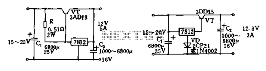
Expand integrated three-terminal regulator block circuit output current method The integrated three-terminal regulator is a versatile component commonly used in power supply circuits to provide a stable output voltage. This regulator typically consists of three terminals: input, output, and ground....
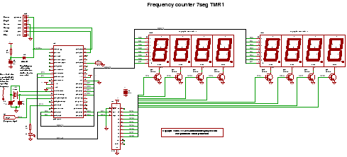
C code for a frequency counter circuit operating up to approximately 50 MHz, utilizing a multiplexed seven-segment display and employing Timer 1 to count the edges of the input signal. The frequency counter circuit described operates effectively within the range...
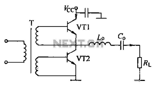
A complementary voltage switching Class D amplifier circuit is presented. Transistors VT1 and VT2 are 3DA12 types, while another transistor, VT3, is of the 3DK41C type. The collector is connected to a constant DC voltage of 12V. The input...