
Band decoder circuit diagram

The described circuit involves an amplifier and an attenuator that work together to control a video detector, specifically tailored for synchronization channels. In this configuration, the synchronization channel is crucial for maintaining the timing and integrity of the video signal. The amplifier is responsible for boosting the signal strength, while the attenuator adjusts the signal level to prevent distortion or saturation in the video processing stage.
Within the synchronization interval, the gain circuit plays a pivotal role. It is designed to dynamically adjust the amplification based on the incoming signal's characteristics. This ensures that the video signal remains within optimal levels for processing, particularly during periods of high activity or signal fluctuations. By increasing the gain during these intervals, the circuit enhances the clarity and reliability of the synchronization signal, which is essential for proper video decoding and display.
In practical applications, this circuit can be integrated into various video processing systems, including television receivers, video conferencing equipment, and broadcast transmission systems. The design should incorporate feedback mechanisms to monitor the output and adjust the gain accordingly, ensuring consistent performance across different operating conditions. Additionally, careful selection of components such as operational amplifiers, resistors, and capacitors is necessary to achieve the desired frequency response and signal integrity.
Overall, this amplifier and attenuator configuration is critical for effective video signal management, ensuring that synchronization is maintained and that the resultant video output is of high quality.The circuit amplifier and an attenuator control video detector consists of a composition for synchronization channel, the synchronization interval, the gain circuit is increased.
Related Circuits
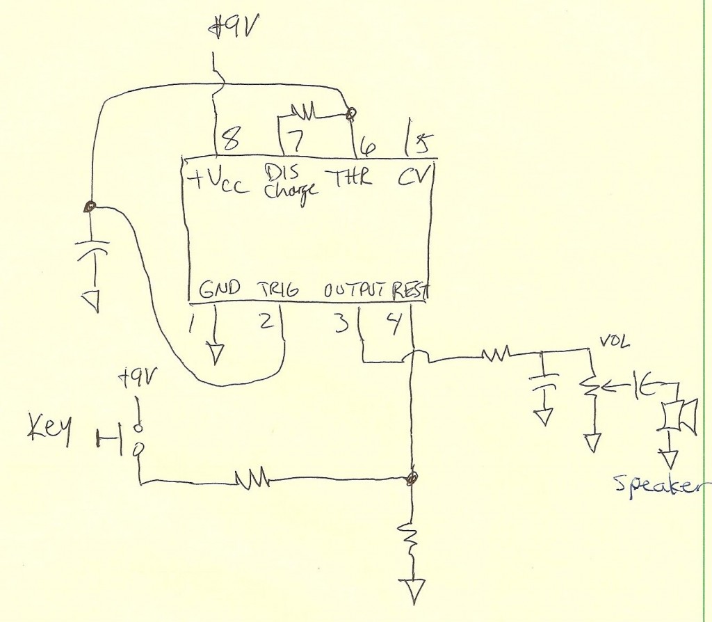
A code practice oscillator was built some time ago, and there is a vague recollection of the project. It featured a straight key that plugged directly into the key jack. Upon opening the device, a circuit board populated with...
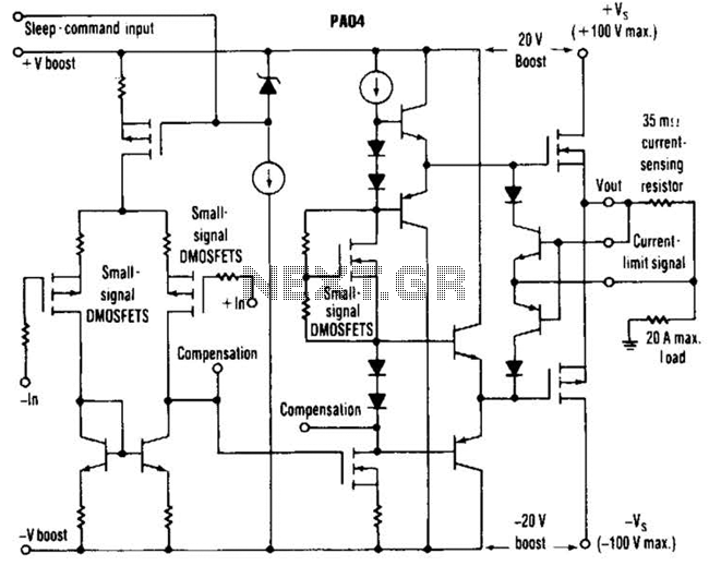
This circuit from Apex Microtechnology can deliver 180 V peak-to-peak at 90 kHz into a 4-ohm load. The PA04 can deliver 400 watts RMS into an 8-ohm load with low total harmonic distortion at frequencies exceeding 20 kHz. The circuit...
This document describes a 100 Watt inverter circuit that utilizes a minimal number of components. The circuit employs the CD 4047 integrated circuit (IC) from Texas Instruments to generate 100 Hz pulses, along with four 2N3055 transistors that drive...
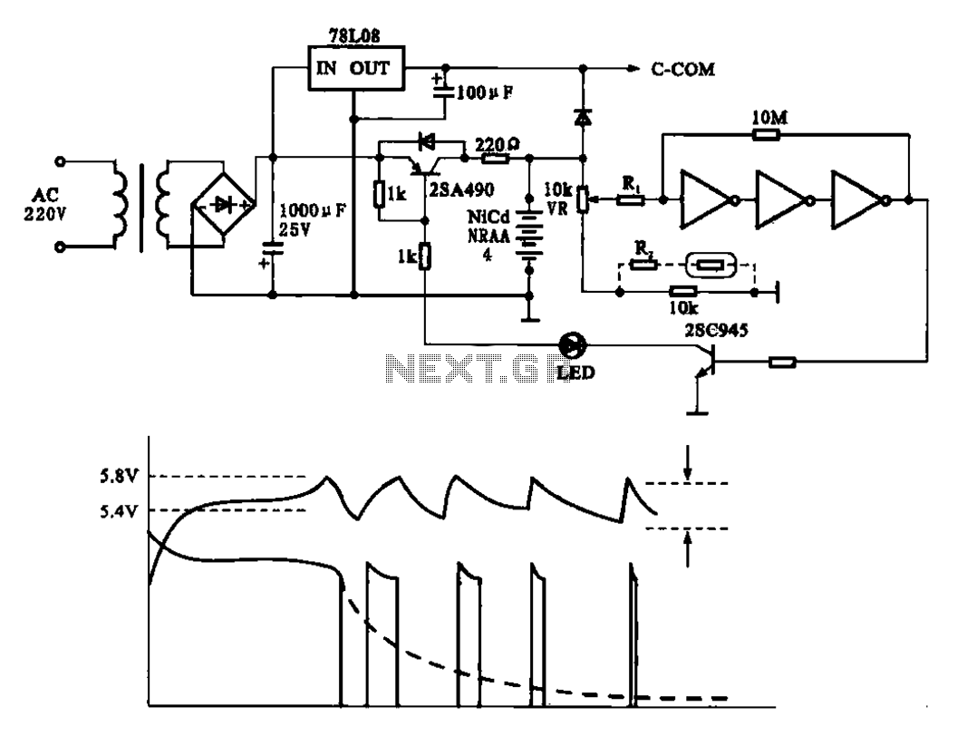
Fast charging circuit that illustrates voltage and current waveforms along with the configuration of the fast charge circuit for the charger. The detection and control circuit consists of three inverters (GMOS) from integrated circuits, enabling automatic control functions. The fast...
This is the large controller utilized for the game Steel Battalion for the Xbox. The schematic diagram was sourced from an individual named Alpha who created it for his own use. The Steel Battalion controller is a specialized input device...
This article describes a circuit for a simple single-cell lithium-ion battery charger utilizing the LP2391 regulator IC. The circuit presented is designed for charging a single-cell lithium-ion battery efficiently. The LP2391 is a linear voltage regulator that provides a constant...