
Circuit From the Past

The code practice oscillator is a fundamental device used by amateur radio operators for learning and practicing Morse Code. The heart of this circuit is the 555 timer, configured in astable mode to generate a continuous square wave output at a frequency determined by the resistors and capacitor connected to it. The frequency can be adjusted to suit the operator's practice needs, typically falling within the range of 300 Hz to 1000 Hz, which is ideal for Morse Code transmission.
The low-pass RC filter following the 555 timer output serves to convert the square wave into a more sinusoidal waveform, which is more pleasant to listen to when transmitted through a speaker. The filter's cutoff frequency is designed to allow the fundamental frequency of the Morse tone to pass while attenuating higher harmonics, resulting in a cleaner sound.
The integration of the straight key into the circuit allows for manual control of the oscillator. When the key is pressed, it connects to the reset pin of the 555 timer, momentarily stopping the oscillation. This feature ensures that each press of the key produces a clean tone without any initial frequency chirp, which could confuse the operator during practice. The reset functionality is critical for maintaining the integrity of the Morse signals being practiced, as it allows the operator to start and stop the tone precisely.
In summary, the code practice oscillator is a straightforward yet effective tool for Morse Code training, utilizing a 555 timer for signal generation, an RC filter for sound quality enhancement, and a straight key for user interaction, all housed within a compact and user-friendly design.A Code Practice Oscillator and that I must have built it some time ago. I had a vague recollection of the project. It certainly looked like something I might have built. There was a straight key in the same box that plugged right into the key jack. I opened the inside and found this circuit board populated with through-hole parts. Replacing the 9V battery with a fresh one, the circuit came to life. A little action on the key and the sound of Morse Code filled the room. I was curious about the design. There is one integrated circuit on the board but it was labeled only with a proprietary part number. What would I have used to built a code practice oscillator Probably a good old 555 timer, so I pulled up an online datasheet for that part and got its pin out. The circuit is not complete ” I just sketched out enough to confirm that the design was based on the 555 timer.
There is a lowpass RC filter on the 555 output to round out the square wave before it is fed to the speaker. It`s interesting that the key connects to the reset pin on the IC. I think this was to ensure a clean start up of the oscillator, to eliminate any frequency chirp. This entry was posted on 3 January 2010, 4:30 pm and is filed under Ham Radio. You can follow any responses to this entry through RSS 2. 0. Both comments and pings are currently closed. 🔗 External reference
Related Circuits
Digital counters have various applications in electronic circuits. In digital electronics, counters are utilized in different situations. This article presents the concept of a ring counter circuit, which functions as a register counter. An animation and simulation video of...
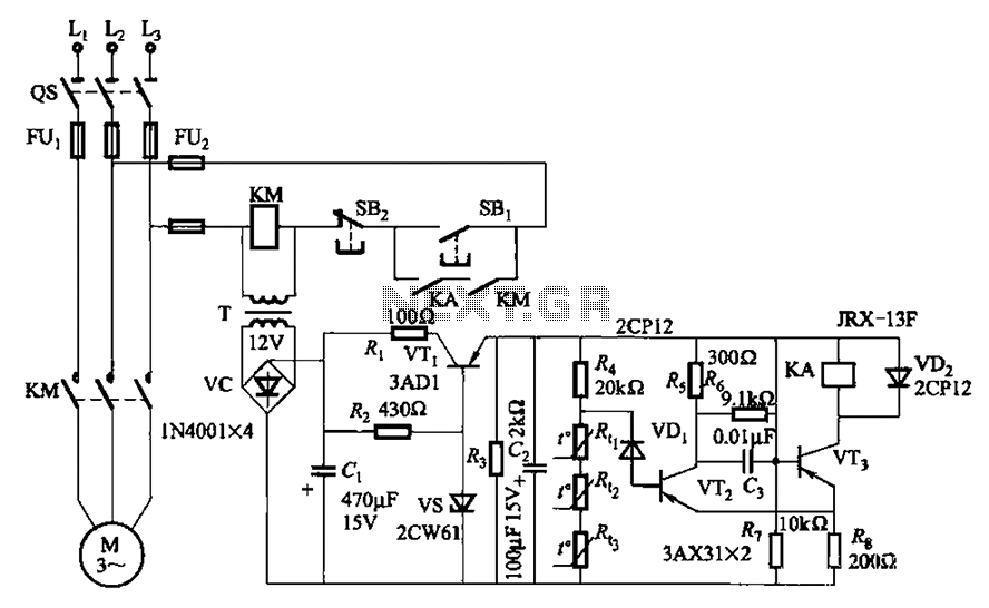
A P-type transistor (VT2, VT3) and other components form a common emitter-coupled trigger, functioning as a Schmitt trigger device. This setup serves as a switching circuit to detect changes in the resistance of a PTC thermistor, thereby controlling the...

This circuit is not visually appealing nor easy to implement, requiring considerable effort. The stepper motor consists of two coils, necessitating the use of two LMD18245 chips to manage the current flow through these coils. It is noteworthy that...
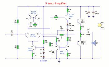
The diagram illustrates a 5W audio amplifier circuit constructed using power transistors BD139 and BD140 for the final amplification stage. This compact amplifier serves as a general-purpose amplifier suitable for applications such as computer audio, radio, MP3 players, and...
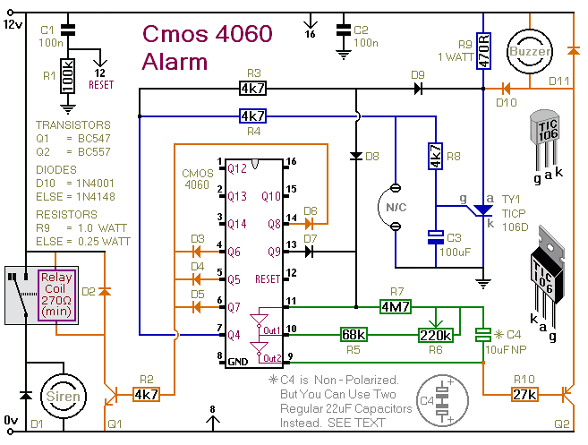
This is a single-zone alarm system featuring automatic exit, entry, and siren cut-off timers. It is designed to accommodate various types of normally-closed input devices, including magnetic reed contacts, foil tape, and passive infrared sensors (PIRs). Additionally, it is...

The circuit shown in Figure 3-139 utilizes a rectifier diode brake for neutral grounding in a three-phase, four-wire power supply system. The circuit employs a rectifier diode configuration to achieve effective neutral grounding, which is crucial for maintaining system stability...