
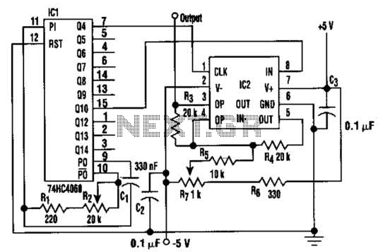
Band-pass filter is a circuit diagram of a single channel

The described band-pass filter is designed to allow signals within a specified frequency range to pass while attenuating frequencies outside this range. In this case, the filter is tailored for audio signals, making it suitable for applications such as audio processing and sound engineering.
The circuit typically consists of passive components such as resistors, capacitors, and possibly inductors, configured to achieve the desired frequency response. The choice of component values is critical in determining the performance characteristics of the filter, including the bandwidth and roll-off rates.
For this specific band-pass filter, the lower cutoff frequency (fL) of 50 Hz suggests that frequencies below this point will be significantly attenuated. This is beneficial for eliminating low-frequency noise and rumble that can interfere with audio clarity. Conversely, the upper cutoff frequency (fH) of 13 kHz indicates that frequencies above this threshold will also be attenuated, which can help in reducing high-frequency hiss and distortion.
To construct the circuit, the following steps are typically involved:
1. Select appropriate resistor and capacitor values to set the fL and fH according to the desired specifications.
2. Connect the components in the correct configuration, often using a combination of series and parallel arrangements to achieve the desired filter characteristics.
3. Test the filter with an audio signal generator and an oscilloscope to verify the performance and ensure that the filter meets the specified frequency response.
Overall, this band-pass filter design is essential for applications where specific frequency components of an audio signal need to be isolated and enhanced while minimizing unwanted noise from other frequency ranges. Band-pass filter is a circuit diagram of a single channel described in this article, that the audio band-pass filter circuit diagram. Its fH 50Hz;, fl 13kHz, as shown below.
Related Circuits
In this circuit, a square wave is filtered using a high-order low-pass filter designed to eliminate most harmonics of the waveform at a -3 dB frequency. Consequently, the output of the filter is a fundamental sine wave. This technique...
For the shorter wavelength VHF and UHF bands, it is more practical to construct complex antennas such as a single-band Slim Jim or Yagis. Various projects include creating an electronic unit, as it is necessary for the Intermediate Level...
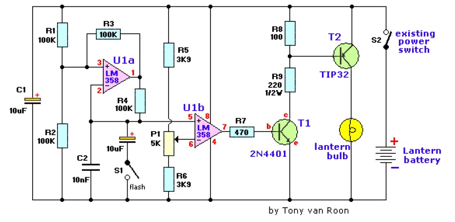
The electronic lantern control circuit enhances an existing battery-powered lantern or flashlight, or can be incorporated into a custom design, by providing high-efficiency dimming and flashing capabilities. This circuit is particularly useful in automotive applications, serving as an effective...
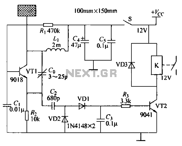
A capacitive proximity controller typically consists of a radio frequency oscillation circuit and a detection plate. The circuit is constructed using discrete components for capacitive proximity sensing detection. The transistor VT1, along with surrounding components, forms a radio frequency...
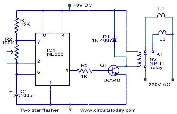
A circuit designed to alternately flash two Christmas stars is presented. The NE555 integrated circuit (IC1) is configured as an astable multivibrator. When IC1 outputs a positive pulse, transistor Q1 becomes conductive, activating relay K1. Consequently, lamp L2, connected...
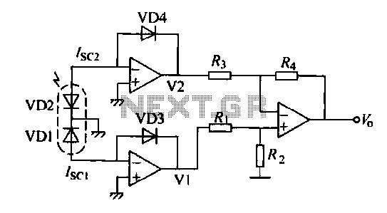
The operation of a semiconductor color sensor can be summarized as follows. The figure illustrates the spectral response curve of two photodiodes that intersect at a specific wavelength. When light of this wavelength is incident on the photodiodes, the...