
Band Pass Filter Tutorial

The passive band pass filter circuit is a fundamental electronic component that allows signals within a specific frequency range to pass through while attenuating signals outside that range. This type of filter is particularly useful in applications such as audio processing, radio communications, and signal conditioning.
The passive RC band pass filter is typically constructed using resistors (R) and capacitors (C). The first-order frequency response of this filter can be analyzed to understand its behavior in the frequency domain. The configuration generally consists of a series capacitor followed by a resistor connected to ground, creating a high-pass filter effect, which is then combined with a parallel resonant circuit to achieve the desired band pass characteristics.
The frequency response of the passive RC band pass filter can be characterized by two critical frequencies: the lower cutoff frequency (f_L) and the upper cutoff frequency (f_H). The lower cutoff frequency is determined by the resistor and capacitor values, while the upper cutoff frequency is influenced by the reactive components in the circuit. The Bode plot, which graphically represents the gain and phase shift of the filter across a range of frequencies, provides valuable insights into the filter's performance. The plot typically shows a rise in gain at frequencies between f_L and f_H, with a roll-off outside this range.
In practical applications, the design of a passive band pass filter requires careful selection of resistor and capacitor values to achieve the desired frequency response. The quality factor (Q) of the filter, which indicates the selectivity of the filter, can also be adjusted by modifying these component values. Overall, the passive RC band pass filter serves as a crucial element in various electronic systems, enabling effective signal processing and management.Electronics Tutorial about the Passive Band Pass Filter Circuit, including Passive RC Band Pass Filter First Order Frequency Response and Bode Plot.. 🔗 External reference
Related Circuits

There are two types of preamplifiers for magnetic phono cartridges. An example of the most common type is the one described in the March 2002 issue of SIL. Preamplifiers for magnetic phono cartridges serve the critical function of amplifying the...
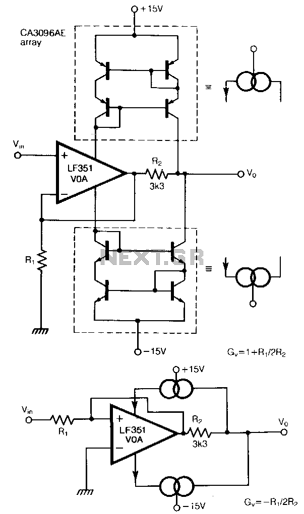
The traditional restriction of constant gain-bandwidth products for a voltage amplifier can be overcome by employing feedback around a current amplifier. Two current mirrors, constructed from transistors in a CA3096AE array, effectively turn the LF351 operational amplifier into a...
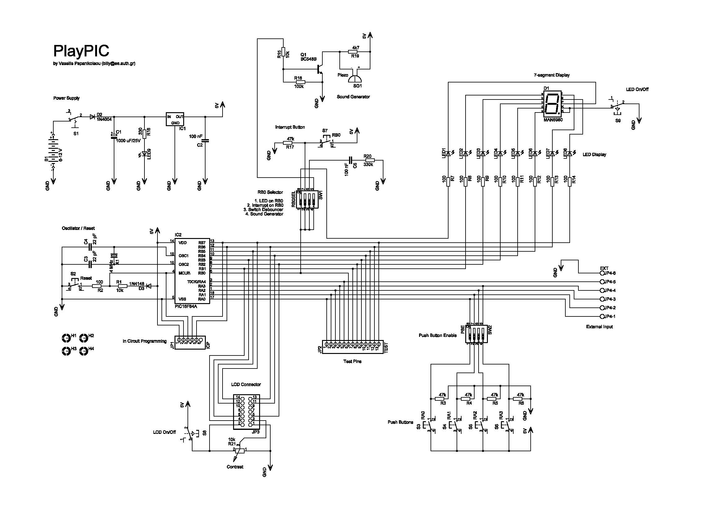
This is a new design of a tutorial board based on the popular PIC16F84A microcontroller. It features eight single LEDs, a 7-segment display, an LCD display, and five push buttons. It is an ideal solution for the beginner to...
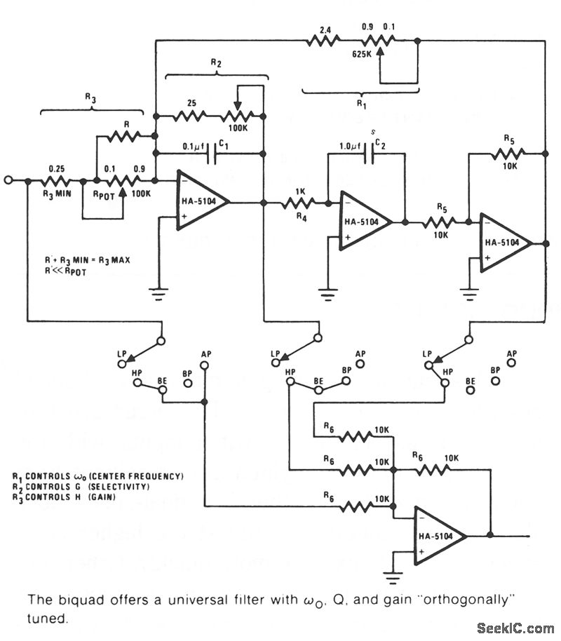
The Biquad consists of two successive integration stages followed by an inverting stage. The entire configuration includes a feedback loop from the front to the back, with resistor R1 primarily responsible for controlling the center frequency, fo. The first...
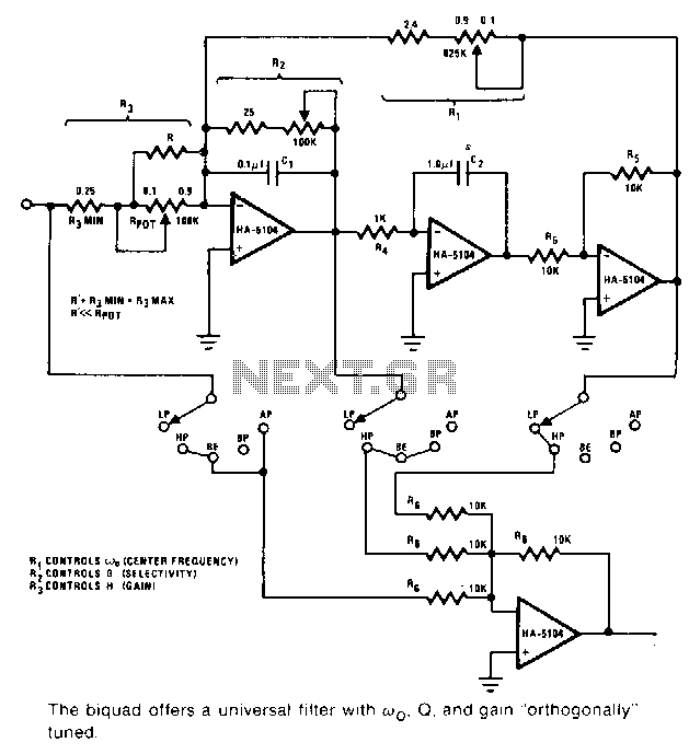
This universal filter provides low-pass, high-pass, bandpass, band elimination, and all-pass functions. The Biquad consists of two successive integration stages followed by an inverting stage. The entire system features a feedback loop from the front to the back, primarily...
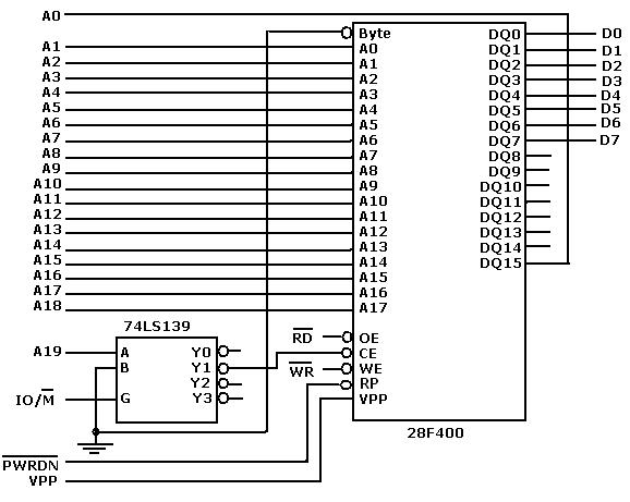
Flash memory, also known as flash RAM, is a type of non-volatile semiconductor memory device that retains stored data even when not powered. It is an enhanced version of electrically erasable programmable read-only memory (EEPROM). The primary distinction between...