
PlayPIC Tutorial

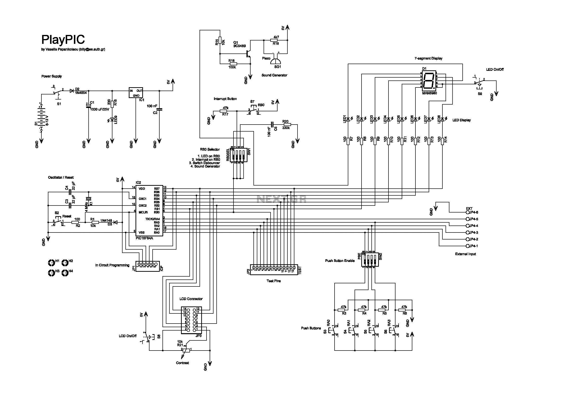
- S1 switches the board on and off. When on, the indicator LED LED9 is lit.
- S2 resets the microcontroller.
- S8 switches the LCD display on and off.
- S9 switches the eight individual LEDs AND the 7-segment display on and off.
- Push buttons S3 to S6 correspond to RA0-RA3 inputs. They are enabled or disabled by the SW2 dip switch.
- The SW1 dip switch enables or disables the following features:
1. Connects RB0 (used as output) to LED1.
2. Connects RB0 (used as interrupt input) to S7.
3. Enables the debouncing circuit for interrupt switch S7.
4. Connects RB0 (used as output) to the buzzer.
This dip switch must be either 1000 or 0100 or 0110 or 0001.
- The 7-segment display is always connected to the individual LEDs. Its seven segments correspond to LED2 to LED8 (RB1 to RB7) and the decimal dot to LED1 (RB0). This correspondence enables the 7-segment display to work together with the interrupt switch S7, which is connected to RB0.
- JP4 is a 6-screw external input connector for RA0-RA4. When used, the corresponding input switches S3-S6 must be turned off by SW2. The last screw is ground.
- JP2 is a 14-pin test terminal. A voltmeter or logic analyzer can be connected any time to monitor the signal traffic in the circuit. The last pin is ground.
- JP1 is the ICP header. When in-circuit programming is performed, the board must be OFF (by S1), as well as the LCD (by S8) and LEDs (by S9).
- JP3 is a 14-pin connector for the LCD module. Contrast can be adjusted by trimmer R21.
- The board can be powered either by a 9V battery or a 6-12 V power supply.
PDF versions of the schematic and PCB are included. The board has been successfully built and it is depicted in the following photos:
This tutorial board is designed to facilitate learning and experimentation with the PIC16F84A microcontroller. The architecture includes various components that provide a comprehensive platform for users to explore microcontroller programming and interfacing.
The microcontroller itself is at the heart of the board, controlling all operations and interfacing with the peripherals. The eight single LEDs serve as visual indicators for various states or outputs, while the 7-segment display is utilized for numeric output, enhancing the user interface. The LCD display further allows for more complex text-based interactions, suitable for displaying messages or prompts during programming exercises.
The push buttons S1 through S6 provide user input, enabling interaction with the microcontroller. The functionality of these buttons can be toggled via the SW2 dip switch, allowing for flexible configurations depending on the learning objectives. The SW1 dip switch offers additional control over specific features, such as connecting outputs to LEDs or enabling interrupts, which is crucial for understanding real-time processing and event-driven programming.
JP4, JP2, JP1, and JP3 connectors provide extensive interfacing capabilities. JP4 allows for external input connections, while JP2 serves as a test point for monitoring signals, which is essential for debugging and understanding circuit behavior. The ICP header (JP1) simplifies the programming process, allowing users to update the microcontroller's firmware without physical removal, which is particularly beneficial for iterative development and learning.
Power supply options enhance the board's versatility, accommodating both battery and external supply configurations, which is important for different project environments or user preferences.
Overall, this tutorial board is a well-rounded educational tool, promoting hands-on experience with microcontroller programming, circuit design, and debugging techniques. The included documentation and schematic files further support users in their learning journey, providing a solid foundation for future projects in embedded systems.This is a new design of a tutorial board based on the popular PIC16F84A microcontroller. It features eight single leds, a 7-segment display, an LCD display and five push buttons. It is an ideal solution for the beginner to take his/her first programming steps in the world of microcontrollers. Having an in-circuit-programming (ICP) header, it can be easily reprogrammed without unplugging the microcontroller each time, provided that the programmer also supports this feature (like OziPic'er).
Feature Description - S1 switches the board on and off. When on, the indicator led LED9 is lit. - S2 resets the microcontroller. - S8 switches the LCD display on and off - S9 switches the eight individual leds AND the 7-segment display on and off. - Push buttons S3 to S6 correspond to RA0-RA3 inputs. They are enabled or disabled by the SW2 dip switch. - The SW1 dip switch enables or disables the following features : 1. Connects RB0 (used as output) to LED1. 2. Connects RB0 (used as interrupt input) to S7. 3. Enables the debouncing circuit for interrupt switch S7. 4. Connects RB0 (used as output) to the buzzer. This dip switch must be either 1000 or 0100 or 0110 or 0001. - The 7-segment display is always connected to the individual leds. Its seven segments correspond to LED2 to LED8 (RB1 to RB7) and the decimal dot to LED1 (RB0). This correspondence enables the 7-segment display to work together with the interrupt switch S7, which is connected to RB0.
- JP4 is an 6-screw external input connector for RA0-RA4. When used, the corresponding input switches S3-S6 must be turned off by SW2. Last screw is ground. - JP2 is a 14 pin test terminal. A voltmeter or logic analyzer can be connected any time to monitor the signal traffic in the circuit. Last pin is ground. - JP1 is the ICP header. When in-circuit-programming is performed, the board must be OFF (by S1), as well as the LCD (by S8) and leds (by S9).
- JP3 is a 14-pin connector for the LCD module. Contrast can be adjusted by trimmer R21. - The board can be powered either by a 9V battery or a 6-12 V power supply. PDF versions of the schematic and PCB are included. The board has been sucessfully build and it is depicted on the following photos : 🔗 External reference
Related Circuits
This is a new design of a tutorial board based on the popular PIC16F84A microcontroller. It features eight single LEDs, a 7-segment display, an LCD display, and five push buttons. It is an ideal solution for beginners to take...
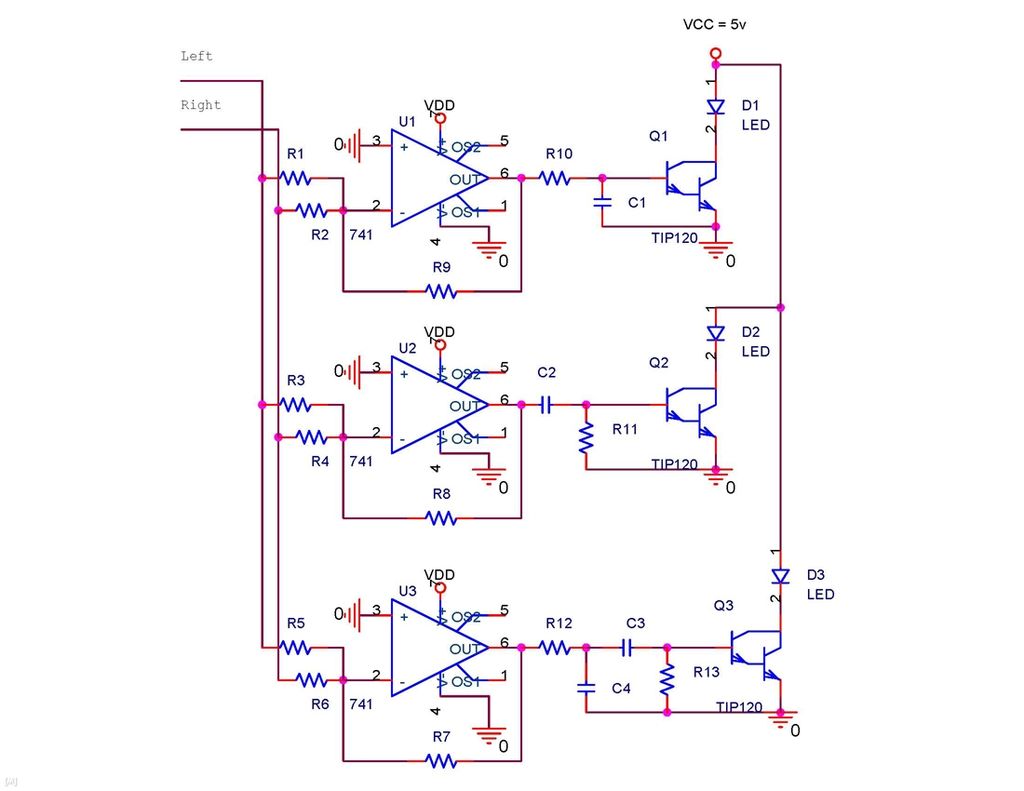
It is possible to synchronize the LEDs so that the speakers continue to play loudly while the LEDs are not always illuminated during music playback. The individual has a solid understanding of electrical concepts and is seeking a method...
This is a brief guide to help users begin with KiCAD. The tutorial focuses on a simple astable multivibrator circuit utilizing the 555 timer IC. The astable multivibrator circuit using the 555 timer IC is a fundamental electronic configuration that...
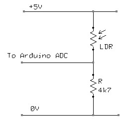
A Light Dependent Resistor (LDR) is utilized to create a simple nightlight for children's bedrooms that automatically turns on in darkness and off in light. The resistance of an LDR varies based on the light intensity it receives. In...
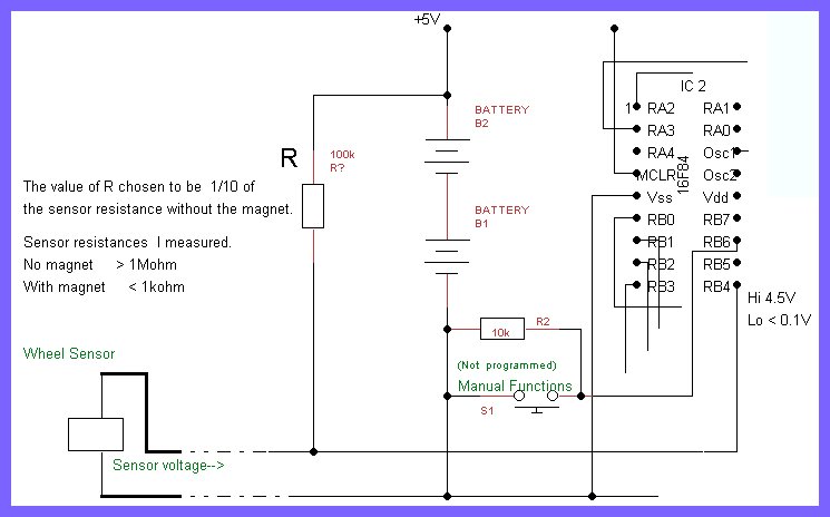
The printed circuit board (PCB) designed is large and provides ample space for modifications and additional components. However, to achieve the goal of integrating it into a real bicycle, its size presents challenges. Earlier discussions highlighted the importance of...
Current sensing involves detecting the amount of current being used by a specific circuit or device. It is particularly useful for assessing the power consumption of various components within a robotic system. Although not commonly required in robotics, current...