
Bandwidth reduction of DXTV video

The design of an effective IF strip in a TV receiver is critical for optimizing signal reception, particularly in crowded VHF bands. The IF strip must be capable of amplifying the incoming ~35 MHz IF signal while maintaining a balance between gain and noise performance. The architecture typically includes several stages of amplification, which can be implemented using discrete components or integrated circuits, depending on the receiver's design philosophy.
A multi-stage IF amplifier configuration is recommended to achieve the necessary gain while minimizing noise. In valve receivers, three stages are optimal, while solid-state designs may benefit from four stages to accommodate the higher gain requirements. The inclusion of additional gain/shaping stages before the main IF strip can enhance overall performance, especially in challenging reception conditions.
To combat interference from high-power transmitters, the use of filters and traps is essential. These components should be strategically placed within the IF strip to attenuate unwanted signals from adjacent channels. A combination of low-pass, high-pass, and notch filters can be employed to create a robust filtering solution that enhances adjacent channel rejection. The design should account for the possibility of strong signals appearing on adjacent channels, particularly during enhanced propagation conditions.
The choice of bandwidth is also a critical design consideration. A narrower bandwidth, such as that offered by modified System A receivers, allows for improved gain and a lower noise figure, which is particularly advantageous for weak signal reception. However, this design choice may sacrifice some high-frequency detail when strong signals are present. The integration of bandwidth switching capabilities could provide flexibility, allowing the user to select the appropriate bandwidth based on current reception conditions.
Overall, the design of the IF strip requires careful consideration of amplification stages, filtering strategies, and bandwidth management to ensure optimal performance in diverse reception scenarios.DX TV enthusiasts often have to deal with relatively crowded VHF bands. In these instances, reduced TV receiver bandwidth results in greater selectivity. The other advantage of bandwidth reduction is improved signal to noise ratio. This results in less noise and distortion of the DX TV picture. Bandwidth reduction is especially useful for weak sig nal modes, such as meteor scatter. Although bandwidth reduction is equally beneficial for TV and FM audio, this article concentrates on TV video. The IF (intermediate frequency amplifiers) strip accepts the ~35 MHz IF output from the VHF (or UHF) tuner and amplifies the required signal to approximately one volt at the detector prior to feeding the video amplifiers(s).
It is within this section that the main IF response is determined; the VHF tuner consists of effectively wide band circuits. In passing, some earlier UK dual standard TV receivers utilised the VHF tuner in whole or part to act as an IF preamplifier stage when operating at UHF.
If a valve receiver is used then 3 vision IF stages are ideal and if possible 4 stages in the case of a solid state receiver fitted with discrete devises - though with present day IC technology distributed in the mass produced TV receiver an additional IF gain/shaping stage could possibly be fitted prior to the main IF strip input - see later. This number of stages if necessary to obtain the required gain/bandwidth performance; bearing in mind the transmitted signal information may have a bandwidth up to 8 MHz.
Although weak signals produce problems undoubtedly an equal problem is interference from high power transmitters, thus effectively limiting the use of high gain aerial amplifiers due to various forms of adjacent and co-channel interference. One way of surmounting such a problem is to include various filters and traps within the IF strip, to remove the offending interference from adjacent channels and frequencies.
Generally most receivers will have insufficient filtering and additional traps can be added to improve the adjacent channel rejection. If one particular transmitter causes a problem, an aerial notch filter can be fitted, but it should be borne in mind that during periods of enhanced reception, strong signals are likely to appear on otherwise unoccupied channels - producing further problems.
Consequently the IF strip should incorporate all the filtering and traps necessary to give good adjacent rejection either side of any channel in use. It had become practise within the United Kingdom to make use of suitably modified System A receivers, with their narrower bandwidth video IF strip (3 MHz bandwidth).
Such a narrow IF bandwidth results in an increased gain with considerably lower noise figure, allowing reception of extremely weak signals, which on a System B receiver (5 MHz video bandwidth) would be marred by noise. This does tend to show a lack of HF detail if the signal becomes extremely strong but the loss is well worthwhile with marginal signals.
An additional advantage is that with the multiplicity of transmission standards within Europe and closely adjacent channel allocations, a narrow IF bandwidth receiver is able to tune to each signal, whereas with a system B receiver, adjacent channels tend to float over each other (an example being chE2/R1). The advantage of a narrow bandwidth is only too obvious during a prolonged Sporadic E opening! Where possible the provision of adding wide/narrow bandwidth switching within the IF strip should be investigated.
With a narrow video IF bandwidth the sound channel of System B and other similar standards using intercarrier sound will of course be lost. Printed circuit IF coils are now common, with little or no means of adjustment, and the fitting of multi-purpose integrated circuits in IF strips had dispensed with many of the tuned circuits once associated with this part of the TV receiver.
IF shaping in this latter type of re 🔗 External reference
Related Circuits
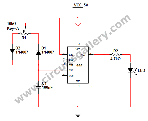
How to change the brightness of an LED. Are LED lights dimmable? Is it possible to adjust the brightness of LEDs? An LED is essentially a diode; when the forward voltage exceeds 0.7 volts, it begins to emit light,...
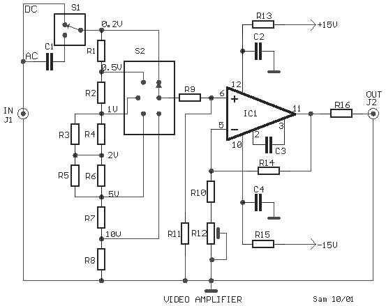
This is a schematic diagram of a video amplifier circuit, built using the very high-speed operational amplifier IC LH0032. Parts List: R1 = 15KΩ, R2, R3, R4 = 10KΩ, R5, R6, R7, R8, R9 = 1KΩ, R10 = 820Ω,...
An NE592 or LM733 is utilized as a general-purpose video amplifier in this schematic. J2 and J3 deliver two anti-phase outputs. R2 functions as a gain control. The bandwidth is approximately 100 MHz. The NE592 and LM733 are integrated circuits...
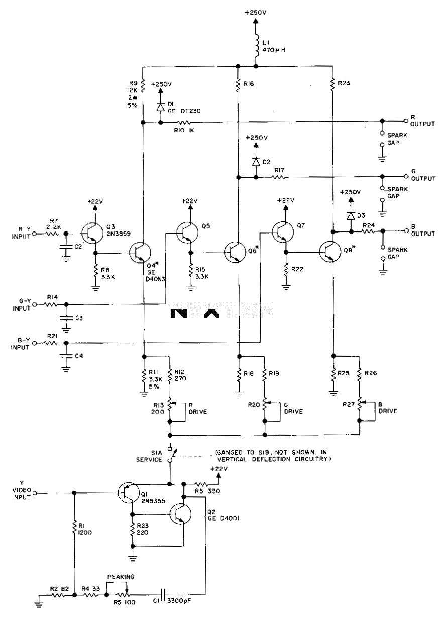
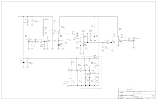
Transistors Q1 and Q2, along with their associated components, provide a low-impedance output necessary for driving the output stages. They enhance gain at high frequencies and improve video peaking for better transient response. Emitter followers Q3, Q5, and Q7...
As a followup to my VCR Pong project, here is a gadget that is actually useful in the Real World! It superimposes the time of day, in "HH MM SS" format, in the bottom right-hand corner of an existing...
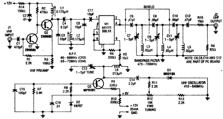
This audio-video circuit enables wireless audio and visual transmission to a television. The television functions as a receiver, eliminating the necessity for a separate monitor. It can also be connected to a VCR or CCD camera, and can be...