
PWM LED Dimmer/ Brightness Control by 555 Timer With Video Simulation

The LED dimmer circuit based on the NE555 timer IC operates in astable mode to produce a PWM signal, which modulates the power delivered to the LED. The frequency of the PWM signal can be adjusted by changing the values of the timing resistors and capacitor in the circuit. The 10kΩ potentiometer allows for fine-tuning of the duty cycle, which directly affects the perceived brightness of the LED. As the duty cycle increases, the LED receives power for a longer duration within each cycle, resulting in increased brightness. Conversely, a lower duty cycle means the LED is powered for a shorter duration, resulting in dimmer light output.
The inclusion of diodes D1 and D2 serves to separate the charging and discharging paths of the capacitor, ensuring that the timing characteristics of the PWM signal remain stable and predictable. This isolation prevents feedback that could otherwise affect the performance of the circuit. The capacitor's charging time, influenced by the resistance and capacitance values, plays a crucial role in determining the frequency and duty cycle of the output signal.
This circuit is not only limited to LED applications but can also be adapted for controlling the brightness of incandescent lamps, making it a versatile solution for various lighting control needs. By adjusting the potentiometer, users can achieve the desired lighting effect, whether for ambiance or practicality, while maintaining the integrity and longevity of the LED components. This approach represents an efficient method for LED brightness control, leveraging the capabilities of the NE555 timer IC and PWM technology.How to change the brightness of aLED Whether led lights are dimmable Is it possible to adjust the brightness of LEDs LED is basically a diode, when the forward voltage exceeds 0. 7 volt, it starts to glow, and if the forward voltage is less than 0. 7 volt, it will be in the OFF state. What happens if we are providing a high voltage to the LED so as to increase the brightness Will it be a practical solution No, it will lead to the burning of LED. So what we can do to adjust the brightness of LEDs Here Circuits Gallery comes with a simple LED brightness control circuit using (Pulse Width Modulation) PWM method.
It is also called PWM LED dimmer circuit diagram. By changing the pulse width of square wave, it is possible to control the brightness of LED. We have already discussed about the PWM signal generation before. Here NE555 timer IC is used to produce PWM signals. Our new circuit is based on 555 timer IC. You can use this circuit as a dimmer switch for LED lights. This PWM concept is also applicable for lamp dimmer switches too. But here we are explaining about 555 led dimmer. At the instant of powering ON the circuit, output will be 5V, because the voltage at the 2nd pin (trigger pin) is less than 1/3 Vcc. [Read Astale Multivibrator for getting familiarized with 555 timer]. At the very next moment, the output voltage will reach the capacitor via the 10k © potentiometer and diode D2 so that the capacitor starts charging with a time constant RdR1C (where Rd is the forward resistance of Diode D2).
Here the charging and discharging path is entirely different since it is isolated by diodes D1 and D2 (refer above images). If the potentiometer midpoint is at 50% (middle), we will able to get 50% duty cycle (square waves of equal pulse width).
🔗 External reference
Related Circuits
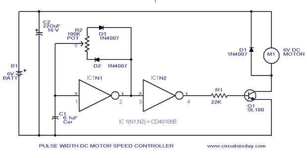
A simple PWM motor speed control circuit with a diagram and schematic for low power DC motors. This easy-to-make PWM DC motor controller is created using the IC CD40106B. The PWM (Pulse Width Modulation) motor speed control circuit utilizes the...
The following circuit illustrates an LM555 integrated circuit (IC) motion detector utilizing infrared sensors. Features include the generation of an infrared pulse modulation at 5 kHz, along with bandwidth control. The LM555 timer IC is a versatile component widely used...
The temperature detection circuit is illustrated in Figure 10. This circuit comprises a temperature sensor, a voltage-to-frequency (V/F) converter, an oscillator, a control program for testing, an alarm system, and a decoding and display circuit. The temperature sensor used...
One of the significant challenges in designing vacuum-tube oscillators is maintaining a constant frequency despite mechanical vibrations, temperature fluctuations, voltage variations in the supply lines, and changes in the load power drawn from the circuit. The effects of variable...
To transmit video and audio signals to multiple televisions simultaneously, a video amplifier splitter utilizing a transistor can be employed. A video amplifier splitter is an electronic device designed to distribute a single video and audio signal to multiple output...
The following circuit illustrates a Video and DVD Modulator in a VHF/UHF electronic diagram. Features include an oscillator that utilizes a transistor for high-frequency operation. The video and DVD modulator circuit serves to convert video signals into a format suitable...