
Basic current to voltage converter

The described circuit operates as a current-to-voltage converter, utilizing an operational amplifier (op-amp) in a summing configuration. The input current (IIN) is introduced at the summing node, which is connected to the inverting input of the op-amp. The op-amp is configured in a feedback loop with resistor R1, which plays a crucial role in determining the output voltage (VOUT). The relationship between the output voltage and input current is linear, making this circuit ideal for precise current measurements.
In this design, the op-amp amplifies the difference between the input current and the bias current, effectively minimizing the impact of the bias current on the output. The output voltage can be monitored to indicate the magnitude of the input current directly, allowing for easy interpretation of the measurement. The scale factor, defined by R1, can be selected based on the desired output voltage range for specific applications. For example, a larger R1 value will yield a higher output voltage for the same input current, which may be beneficial in applications requiring greater voltage levels.
This circuit can be implemented in various measurement systems, where accurate current readings are essential. The simplicity of the design, combined with the op-amp's high input impedance and low output impedance, ensures that the circuit does not significantly load the source being measured, preserving the integrity of the current measurement. Additionally, the circuit can be expanded with additional components, such as filters or additional op-amps, to enhance performance or adapt to specific measurement conditions.With this basic circuit, the input current is fed directly into the summing node (pin 2) and the op-amp output changes to extract the same current from the summing node through R1. The scale factor of this circuit is R1 volts per amp. That is, the output voltage is equal to the input current timesR1. The only conversion error in this circuit is Ib ias, which is summed algebraically with IIN. The basic circuit can be used to measure current directly because: IIN =VOUT/R1. For example, if VOUT is 1 V (or 1000mV), and R1 is 100 ©, IN = 10mA. 🔗 External reference
Related Circuits
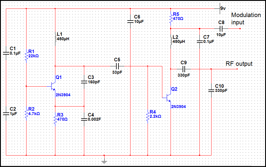
This transmitter is basic but allows the transmission of audio to an AM radio. It consists of an RF oscillator operating in the AM broadcast band, along with a modulator stage that mixes the incoming audio with the RF...
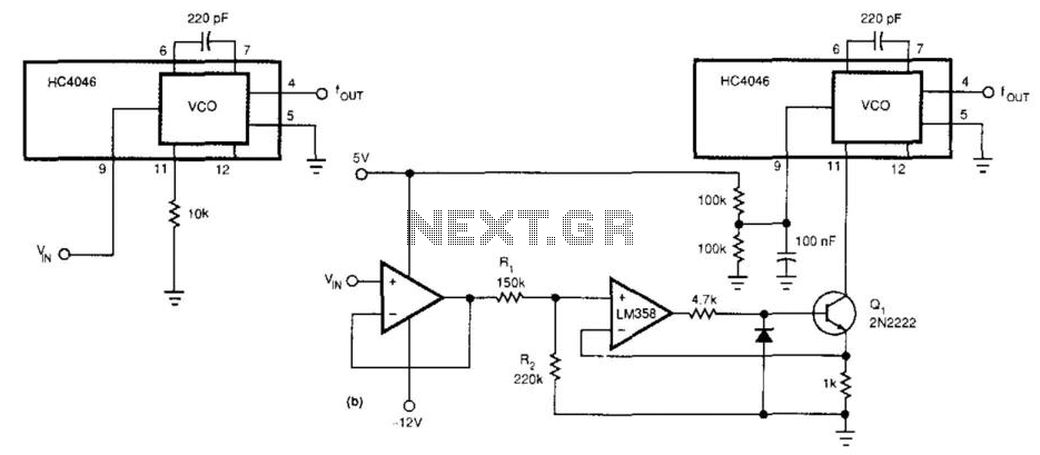
This circuit expands the linear frequency range of an HC4046 from one decade to nearly three decades. An LM358 is utilized as a constant-current sink, replacing the frequency-determining resistor (10 kΩ) connected from pin 9 to ground. For this...
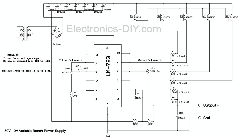
The LM723 current sense and current limit pins (2 and 3) detect a voltage generated by low-resistance current-limiting resistors. When this voltage reaches a specific threshold, the integrated circuit (IC) either shuts down or restricts the power supply output....
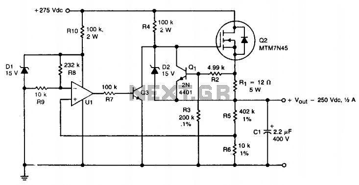
A TMOS MTM7N45 (Q2) is utilized as a series pass element in a linear high voltage supply that accepts +275 V unregulated and produces 250 V regulated with foldback current limiting. A 15 V zener diode (D1) provides the...

This design concept outlines a 12-V DC to 5-V DC (±5%) switched-mode power supply (SMPS). The supply utilizes a 12-V input derived from an array of four 3-V DC, 40-mA solar cells connected in series. The proposed switched-mode power supply...
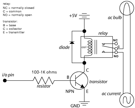
The schematic illustrates the Relay Wiring Circuit Diagram used to control an air conditioner or other high-current devices via a microcontroller. The relay wiring circuit serves as an interface between low-voltage microcontroller signals and high-voltage appliances, such as air conditioners....