
5-Volt RelayCircuit for Controlling AC Current

The relay wiring circuit serves as an interface between low-voltage microcontroller signals and high-voltage appliances, such as air conditioners. This circuit typically consists of a relay module, which includes an electromagnetic switch capable of handling high current. The microcontroller outputs a control signal, often a digital HIGH or LOW, to the relay's input, activating or deactivating the relay coil.
When the microcontroller sends a HIGH signal to the relay, current flows through the relay coil, creating a magnetic field that closes the switch contacts. This action connects the high-voltage power supply to the load—in this case, the air conditioner—allowing it to operate. Conversely, when the microcontroller outputs a LOW signal, the relay coil is de-energized, the magnetic field collapses, and the switch contacts open, disconnecting the power supply from the load.
To ensure safe operation, the circuit may include protective components such as diodes across the relay coil to prevent back EMF when the relay is switched off, as well as fuses or circuit breakers to protect against overcurrent situations. Additionally, opto-isolators may be used to provide electrical isolation between the microcontroller and the high-voltage circuit, enhancing safety and reducing the risk of damage to sensitive components.
The schematic should clearly indicate the connections between the microcontroller, relay module, power supply, and load, along with any necessary components for protection and isolation. Proper labeling of each component and connection will facilitate understanding and implementation of the circuit, ensuring reliable control of high-current devices.The following schematic shows the Relay Wiring Circuit Diagram for controlling an Air Conditioner or other higher high-current device from a microcontroller.. 🔗 External reference
Related Circuits
A detailed discussion on implementing current limiting or foldback current limiting for the linear regulator controllers of the MAX1864. This can also be applied to other discrete regulator designs, including the MAX1865, MAX1964, MAX1965, MAX8513, and MAX8514. To incorporate current...
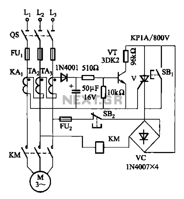
Both circuits are used to control the thyristor contactor KM action to overcome the break phase protection relay prone to malfunction or refuse to move, and enhance the sensitivity and reliability of the protection device. The described circuits are designed...
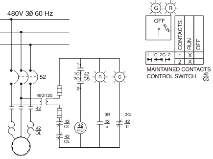
Motor starters generally fall into two categories: full-voltage or reduced-voltage. The choice of which type of starter to use depends on various factors, such as the current-carrying capacity of plant wiring, the ability of plant power supplies to absorb...
The circuit is designed to enable rapid changes in motor speed and direction by utilizing four outputs to drive a MOSFET H-bridge. The lower rail power MOSFETs are N-channel devices, while the upper rail MOSFETs are P-channel. All MOSFETs...
The principles of DC motors are discussed in the beginner and intermediate sections of this tutorial. This section will address the electronics required to interface them with a Basic X microcontroller or other digital chips. The simplest method of...
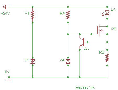
Design a lighting circuit for an indoor garden. There is a 24V input source that needs to be limited to 20V. LA is a series array of LEDs with a total voltage drop of approximately 19.8V. R1 and Z1...