
Basic Dual Polarity Power Supply

The dual polarity power supply circuit is designed to provide both positive and negative voltage outputs from a single transformer. The center-tapped transformer is the key component, featuring a primary winding connected to the AC mains and two equal secondary windings that produce two outputs, typically referred to as the positive and negative voltages.
The circuit utilizes four diodes arranged in a full-wave rectifier configuration. This setup can also be replaced by a single diode bridge rectifier, which simplifies the design by integrating the four diodes into one component. The rectification process converts the alternating current (AC) from the transformer into direct current (DC), producing both positive and negative voltages relative to the center tap.
Following the rectification, four electrolytic capacitors are employed to smooth the output voltage. These capacitors store charge and help reduce voltage ripple, ensuring a more stable DC output. The values of the capacitors should be selected based on the load requirements and the desired level of ripple voltage. Typically, larger capacitance values lead to lower ripple, but they also affect the response time of the power supply under load changes.
Overall, this dual polarity power supply circuit is fundamental in various electronic applications, including operational amplifiers, analog signal processing, and other devices that require dual voltage supplies. Proper selection of each component, including the transformer ratings, diode specifications, and capacitor values, is critical to the successful implementation of this circuit.This is a very basic dual polarity power supply circuit diagram. It just need the following components: - A Center Tapped Transformer - Diode rectifier 4 units (or diode bridge 1 unit) - Electrolityc capacitor 4 units The value of each comp.. 🔗 External reference
Related Circuits
A circuit is being designed for a DC motor utilizing the following components: 1 x 7805 voltage regulator and 2 x 2N2955 transistors, which are to be paralleled to increase current capacity. The proposed circuit will employ a 7805 voltage...
This dual polarity power supply is easy to build, requires few parts, and is adjustable from 0-15 volts. It is great for powering op amp circuits, as well as other circuits that require a dual supply voltage. The dual polarity...
A circuit for a bicycle horn utilizing a low-cost telecom ringer chip is presented. This design can be powered by a bicycle dynamo, eliminating the need for frequently replaced batteries. The circuit includes a half-wave voltage-doubler section formed by...
Applying the filtered and rectified AC input to a high-input-voltage linear regulator is the simplest way to produce a low current level from an AC source. The process of converting an AC source to a low current level using a...
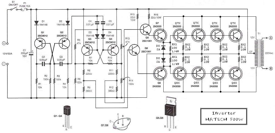
This is the schematic diagram of a 500W power inverter circuit built using 10 pieces of well-known NPN power transistors, 2N3055, to amplify the AC signal produced by a multivibrator. The frequency generator/multivibrator is also constructed using transistors. All...
The circuit diagram was designed to create a power supply without utilizing any transformer circuit. This circuit illustrates the advantages as well as the limitations of transformerless power supplies. The transformerless power supply circuit typically employs a capacitive dropper method...