
Basic power supply schematic

C1 = 2200 ?F/35 V (see text) C2, C3 = 100 nF ?F/35 C4 = 10 V (see text) Br1 = 4x 1N4002 or 1N5401 (see text) VR1 = 78xx T1 = Transformer
The described circuit is a basic linear voltage regulator utilizing the 78xx series integrated circuit (IC), which is widely used for providing stable output voltages in various electronic applications. The 78xx series includes multiple variants, allowing for output voltages of 5V, 12V, 15V, and others, depending on the specific model chosen.
The power supply design begins with a transformer (T1), which steps down the AC mains voltage to a lower AC voltage suitable for rectification. The transformer can have two coils connected in series to achieve the desired output voltage or in parallel to increase the output current capability.
The output from the transformer is then rectified using a bridge rectifier (Br1), which can consist of four 1N4002 diodes or 1N5401 diodes, depending on the output current requirements. The rectified output is then smoothed using a large filter capacitor (C1), which is crucial for reducing ripple voltage. The value of C1 is determined by the output voltage and current; for voltages below 5V, a value of 1000 µF is sufficient, while for voltages above 15V and currents exceeding 1A, a value of 4700 µF is recommended.
C2, a decoupling capacitor of 100 nF, is placed close to the voltage regulator to filter high-frequency noise and ensure stable operation. C3 serves a similar purpose, providing additional stability to the output. C4, rated at 10V, is used if the wiring distance between the power supply and the load exceeds ±15 cm, compensating for potential voltage drops over longer distances.
The voltage regulator (VR1) outputs a fixed voltage, with the maximum output current rated at either 100 mA, 1 A, or 2 A depending on the specific 78xx series model used. It is important to ensure that the components are rated appropriately for the expected supply voltage and output current to prevent overheating and potential failure. Additionally, if the output current exceeds 1 A, the diodes in the bridge rectifier should be replaced with higher-rated diodes such as the 1N5401 to handle the increased load.
A heat sink may be necessary for the voltage regulator to dissipate heat generated during operation, especially when there is a significant difference between the input and output voltages. Proper thermal management is essential to maintain the reliability and longevity of the power supply circuit.The simplest power supply voltage regulator can be created with the 78xx series. The voltage regulator is available in different voltages (see table). The controller is 100 mA, 1 or 2 A provides. C2 is a decoupling capacitor. He must therefore as close to the controller are placed. The parts must be adapted to the supply voltage and current. At low voltages (below 5 V) can be reduced to C1 1000 uF. At voltages above 15 V and 1 A should be C1 4700 uF. With output currents above 1 A, the diodes are replaced by 1N5401. The transformer, the maximum output voltage can provide. The voltage can be supplied by two transformer coils in series. The output current can be doubled by coils in parallel. If the difference between the voltage transformer and the output voltage increases, the drive will be warmer. A larger heat sink than needed. C4 You will apply if the wiring between the power supply and the circuit is greater than ± 15cm C1 = 2200 ?F/35 V (see text) C2, C3 = 100 nF ?F/35 C4 = 10 V (see text) Br1 = 4x 1N4002 or 1N5401 (see text) VR1 = 78xx T1 = Transformer
🔗 External reference
Related Circuits
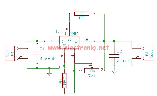
The following circuit illustrates the L200 Regulator Power Supply Circuit Diagram. Features include its use in power supply applications with specified voltage and current. The L200 voltage regulator is a versatile and adjustable linear regulator designed for various power supply...
The UBA2021 can be utilized as a 600 V lamp controller and half-bridge driver integrated circuit (IC) for high-power applications. It is designed for long-life compact fluorescent lamp (CFL) and tubular fluorescent lamp (TL) applications. The UBA2021 is a versatile...
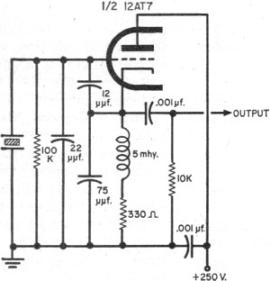
The fundamentals of crystals have not changed since this article appeared in a 1960 edition of Popular Electronics. The methods for growing, cutting, and packaging crystals have evolved significantly. Understanding their operation at the atomic level has also advanced...
To order boards, click to access the ESP Purchase form. Verify the price and postage, then open the order form, fill it in, and print it from your browser. Boards are sold only as a stereo pair and are...
An alternative method for utilizing operational amplifiers (op-amps) to regulate a power supply is illustrated below. The power transformer necessitates an additional winding to provide the op-amps with a bipolar voltage of +/- 8 volts. This negative voltage is...
This circuit is designed to signal the exceeding of a fixed threshold in room noise through a flashing LED. Three fixed levels are selectable: 50, 70, and 85 dB. Two operational amplifiers provide the necessary gain for sounds captured...