
variable voltage and current power supply

The described power supply regulation circuit employs operational amplifiers for precise voltage control and current limiting. The configuration begins with a transformer that provides a dual winding output, delivering both positive and negative voltages necessary for the op-amps. The op-amps utilize these voltages to maintain stable output levels and to monitor the current flowing through the load.
A critical component in this circuit is the 500-ohm potentiometer, which serves as a variable voltage divider. The wiper of the potentiometer is connected to the op-amp's non-inverting input, allowing for dynamic adjustments based on the load conditions. The op-amp's feedback mechanism ensures that the output voltage remains stable even as the load varies.
Current limiting is accomplished through a low-value resistor placed in series with the negative supply line. This resistor enables the detection of voltage drops that correspond to the load current. As the current increases, the op-amp adjusts its output to control the base current of the 2N3053 transistor, which acts as a driver for the larger 2N3055 pass transistor. This arrangement allows for effective regulation of the output current, preventing excessive current flow that could damage the circuit components.
Thermal management is also a crucial aspect of this design. The TIP32 and 2N3055 transistors must be mounted on heat sinks to dissipate the heat generated during operation, particularly under high load conditions. The calculations for heat dissipation are essential for ensuring the longevity and reliability of the components. By adjusting the output voltage and monitoring the load current, the circuit can be optimized for various applications while maintaining safe operating temperatures.
Overall, this power supply regulation circuit exemplifies the versatility of op-amps in power management applications, combining effective current limiting with adjustable output voltage capabilities.Another method of using opamps to regulate a power supply is shown below. The power transformer requires an additional winding to supply the op-amps with a bipolar voltage (+/- 8 volts), and the negative voltage is also used to generate a reference voltage below ground so that the output voltage can be adjusted all the way down to 0. Current limit ing is accomplished by sensing the voltage drop across a small resistor placed in series with the negative supply line. As the current increases, the voltage at the wiper of the 500 ohm pot rises until it becomes equal or slightly more positive than the voltage at the (+) input of the opamp.
The opamp output then moves negative and reduces the voltage at the base of the 2N3053 transistor which in turn reduces the current to the 2N3055 pass transistor so that the current stays at a constant level even if the supply is shorted. Current limiting range is about 0 - 3 amps with components shown. The TIP32 and 2N3055 pass transistors should be mounted on suitable heat sinks and the 0. 2 ohm current sensing resistor should be rated at 2 watts or more. The heat produced by the pass transistor will be the product of the difference in voltage between the input and output, and the load current.
So, for example if the input voltage (at the collector of the pass transistor) is 25 and the output is adjusted for 6 volts and the load is drawing 1 amp, the heat dissipated by the pass transistor would be (25-6) * 1 = 19 watts. In the circuit below, the switch could be set to the 18 volt position to reduce the heat generated to about 12 watts.
🔗 External reference
Related Circuits
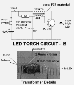
This circuit illustrates a 1.5V LED power supply circuit diagram. Features include the requirement of a step-up transformer (40:60) for easy provision. Components include an integrated circuit (IC). The described circuit functions as a power supply specifically designed for driving...
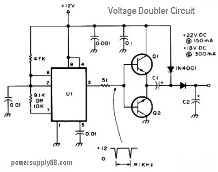
The schematic diagram originates from a 12V DC voltage doubler circuit power supply. This circuit diagram illustrates a DC voltage doubler/DC converter that transforms a 12V DC power supply into 24V DC and 18V DC outputs. It is compatible...
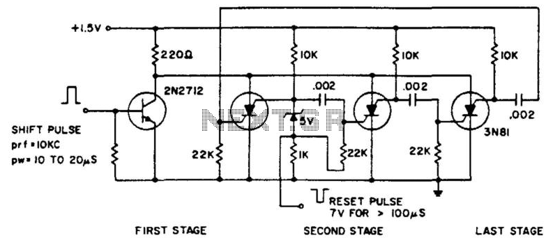
The ring counter operates from 1.0 to 6.0 V and requires only 6 mW at 1.5 V. The reset pulse activates the first stage with its trailing edge. The maximum shift pulse width increases with voltage and approaches 70...
A voltage-controlled oscillator (VCO) is an oscillator whose frequency is regulated by a voltage signal. The VCO discussed here can generate both triangular and square wave outputs. The control voltage can be adjusted between 5 mV and 5 V,...
The simplified circuit [Fig.2] shows that each sub-amplifier consists of two voltage gain stages. The first stage consists of a complementary two stage common emitter [Q1-7] whose gain is about x2.3. The second stage is a current mirror stage [Q13-14]...
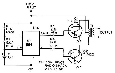
This low-power 25-watt power inverter circuit utilizes only nine electronic components. The inverter converts a DC input voltage ranging from 10V to 16V into a 60Hz, 115V square-wave power output, capable of powering AC electronic devices up to approximately...