
Basic reference bias circuit transistor - negative voltage feedback

The basic reference bias circuit utilizing a transistor with negative voltage feedback is designed to provide a stable output voltage or current that is largely independent of variations in temperature and power supply. The circuit typically consists of a bipolar junction transistor (BJT) configured in a feedback arrangement, where a portion of the output is fed back to the input to maintain stability.
In this configuration, the transistor operates in the active region, where it can amplify the input signal. The negative voltage feedback is achieved by connecting a resistor from the output to the base of the transistor. This resistor forms a voltage divider with the base-emitter junction, effectively reducing the base voltage as the output voltage increases, which in turn decreases the collector current. This feedback mechanism stabilizes the output by counteracting any changes in the load or supply voltage.
The circuit may also include additional components such as capacitors for filtering and resistors to set the biasing conditions. The use of bypass capacitors can help to filter out high-frequency noise, ensuring a clean and stable reference voltage. The values of the resistors and capacitors must be carefully selected to achieve the desired response time and stability of the circuit.
Overall, this basic reference bias circuit is essential in various electronic applications where a reliable and constant reference voltage is required, such as in amplifiers, oscillators, and other analog circuits. It serves as a foundational element in designing more complex electronic systems. Basic reference bias circuit transistor - negative voltage feedback
Related Circuits

The circuit regulates the RMS output voltage across a load, specifically a projection lamp, to 100 volts ±2% for input voltages ranging from 105 to 250 volts AC. This regulation is achieved by indirectly sensing the light output of...
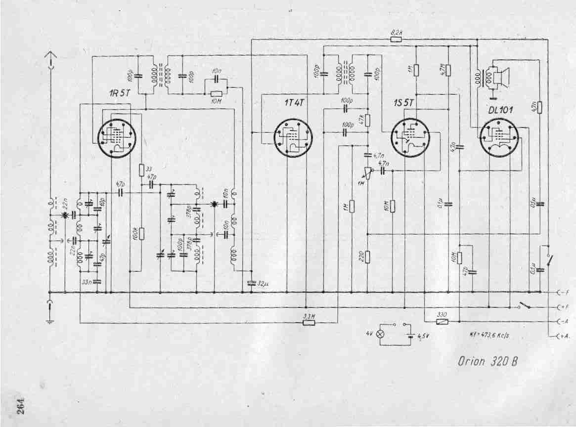
Create a repository of circuits and service data for vintage valve and transistor radios. While many resources are available online, they often come at a cost. The intention is to share circuits and manuals with others rather than profit...

The circuit utilizes the HL-169B voice alarm integrated circuit (IC). It is designed for use in security applications, including glass doors, car doors, and windows, to act as a burglar alarm. When a thief applies force to these items,...
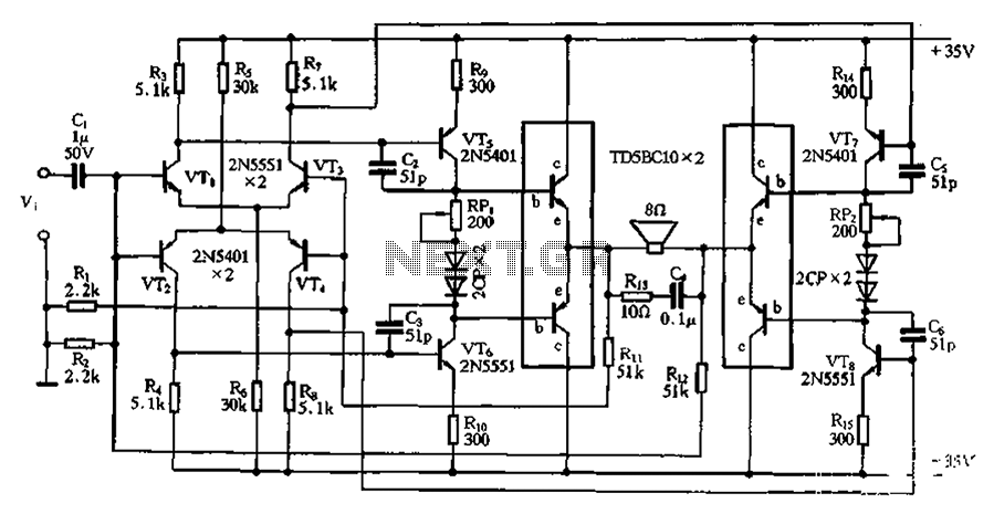
The bridge is a low-frequency push-pull power amplifier circuit with a simple structure, capable of delivering an output power of up to 1W. It can be utilized as an external amplifier for devices such as Walkmans, phones, doorbells, alarms,...
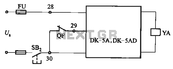
The DK-5A and DK-5AD AC power control circuit is illustrated in Figure 6-77. The figure includes a closing button (SBz) and a line (YA) connected to the closing electromagnet coil (U). This circuit is designed for the operation of...
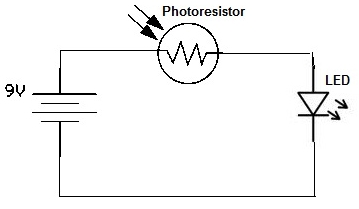
A simple photoresistor circuit will be constructed to demonstrate the operation of a photoresistor, which activates the circuit in the presence of light and deactivates it in darkness. This circuit connects a photoresistor to an LED. When the photoresistor...