
DC bridge amplifier circuit

The described low-frequency push-pull power amplifier circuit is designed for versatility and ease of use. Its output stage employs a BTL configuration, which effectively drives speakers by providing higher output power while minimizing distortion. The complementary symmetry dual differential input stage enhances the linearity of the amplifier, ensuring that the signal remains faithful to the input. By utilizing a double push-pull voltage amplification method, the circuit maximizes efficiency and power handling capabilities, making it suitable for various applications, from personal audio devices to alarm systems.
The choice of the TD5BC10 module for the output stage is particularly advantageous, as it is designed for consistency and reliability in small amplifier applications. This module simplifies the debugging process, allowing hobbyists and engineers to focus on fine-tuning the amplifier's performance rather than grappling with complex configurations. Furthermore, the design allows for the substitution of other high-power transistors, providing flexibility for those who may have specific performance requirements or component availability considerations.
Overall, this low-frequency push-pull power amplifier circuit exemplifies a well-thought-out design that balances simplicity, performance, and adaptability, making it an ideal choice for both amateur and professional applications in the field of audio amplification. Bridge is a low frequency push-pull power amplifier circuit, its structure is very simple, output power up to 1W. Walkman used as an external amplifier, it can serve as phone, doorbell, alarm and other power amplifier o circuit as shown in Figure 2-46. The simple circuit structure, excellent performance, high output power, easy debugging, it is suitable for amateur homemade. VTi ~ VT4 composed of complementary symmetry dual differential input stage, the output stage of BTL structure, the voltage amplifier stage with double push-pull voltage amplification so and BTL amplifier output stage adaptation.
Amplifier output stage uses a small amplifier consistency pairing module TD5BC10, make debugging very simple o may also be similar to this performance of other high-power tube, paired.
Related Circuits
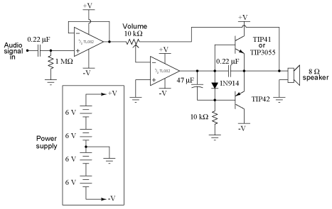
It is advisable to obtain TIP41 and TIP42 transistors, which are closely matched NPN and PNP power transistors with dissipation ratings of 65 watts each. If a TIP41 NPN transistor is unavailable, the TIP3055 (available from Radio Shack) serves...
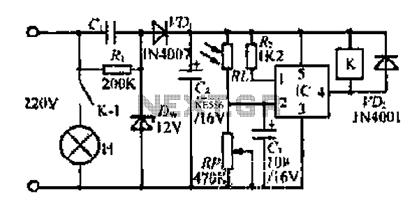
At dawn, light illuminates the photosensitive resistor RL, causing its resistance to decrease. This switch IC (2) exhibits a high electrical footprint. When light is present, the relay K does not activate. At night, in the absence of light,...
The signal from a microphone is too weak for a standard line input. This low-noise DC-coupled microphone amplifier provides a solution for anyone who wants to amplify the microphone signal effectively. A low-noise DC-coupled microphone amplifier is designed to enhance...
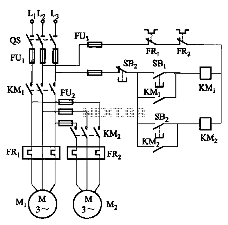
The circuit illustrated in Figure 3-83 demonstrates that the contactor KMi is activated only after it is pulled, which indicates that the motor Mi has started for the first time. Following this, the contactor KM2 is then activated, indicating...
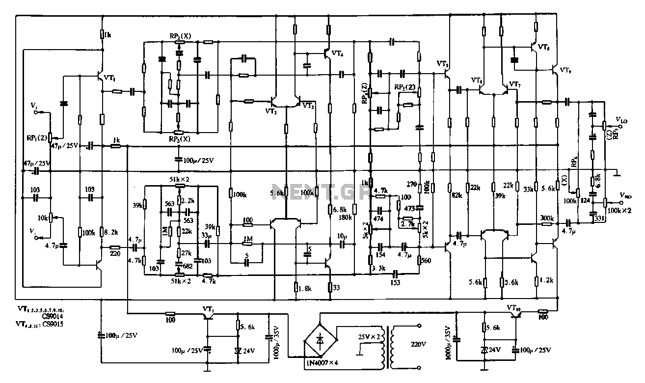
Figure 4-11 illustrates a feedback attenuator that comprises a transistor-based tone control circuit. This circuit features a conventional high and bass control system, along with balance control, volume control, loudness adjustment, and subwoofer control, as well as field sense...
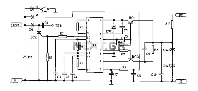
An AC magneto is connected to an external circuit. The output is rectified by diode D1 and stored in capacitor C1. Additional rectification is performed by diodes D4, along with resistors R9 and capacitors C7 and C8, which filter...