
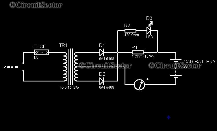
Basic UPS PCB

The circuit operates effectively by integrating several key components that work in harmony to provide a reliable power supply. The transformer TR1 steps down the 240 Volt AC mains voltage to a suitable level for the secondary circuit. The 5 Volt regulated output is achieved through a linear voltage regulator, while the unregulated 12 Volt output is derived directly from the transformer secondary. The inclusion of slow-blow fuse FS1 is critical for safeguarding the circuit against potential short circuits that could compromise the integrity of the power supply.
The LED indicator, which serves as a visual cue for power availability, is designed to be off during power outages, thus signaling the user that the battery is now supplying power. The charging circuitry, composed of resistor R1 and diode D1, is essential for maintaining the battery's charge without overloading it, ensuring longevity and reliability. The circuit's flexibility is further enhanced by the option to substitute different voltage regulators and battery configurations, allowing customization based on specific application requirements.
Overall, this UPS circuit exemplifies a robust solution for maintaining power supply continuity, making it suitable for various electronic applications where uninterrupted power is critical.This circuit is a simple form of the commercial UPS, the circuit provides a constant regulated 5 Volt output and an unregulated 12 Volt supply. In the event of electrical supply line failure the battery takes over, with no spikes on the regulated supply.
This circuit can be adapted for other regulated and unregulated voltages by using different re gulators and batteries. For a 15 Volt regulated supply use two 12 Volt batteries in series and a 7815 regulator. There is a lot of flexibility in this circuit. TR1 has a primary matched to the local electrical supply which is 240 Volts in the UK. The secondary winding should be rated at least 12 Volts at 2 amp, but can be higher, for example 15 Volts. FS1 is a slow blow type and protects against short circuits on the output, or indeed a faulty cell in a rechargeable battery.
LED 1 will light ONLY when the electricity supply is present, with a power failure the LED will go out and output voltage is maintained by the battery. The circuit below simulates a working circuit with mains power applied: Between terminals VP1 and VP3 the nominal unregulated supply is available and a 5 Volt regulated supply between VP1 and VP2.
Resistor R1 and D1 are the charging path for battery B1. D1 and D3 prevent LED1 being illuminated under power fail conditions. The battery is designed to be trickle charged, charging current defined as D2 must be included in the circuit, without D2 the battery would charge from the full supply voltage without current limit, which would cause damage and overheating of some rechargeable batteries. An electrical power outage is simulated below: The ability to maintain the regulated supply with no electrical supply depends on the load taken from the UPS and also the Ampere hour capacity of the battery.
If you were using a 7A/h 12 Volt battery and load from the 5 Volt regulator was 0. 5 Amp (and no load from the unregulated supply) then the regulated supply would be maintained for around 14 hours. Greater A/h capacity batteries would provide a longer standby time, and vice versa. 🔗 External reference
Related Circuits
In today's world, owning a car battery charger at home has become essential. Having one readily available can help prevent starting issues caused by battery problems. While purchasing a commercial battery charger can be expensive, the components required for...
This circuit includes an intermittent siren output with automatic reset functionality. It can be activated manually via a key switch or a concealed switch, or it can be configured to activate automatically when the ignition is turned off. By...
This document presents a well-defined printed circuit board layout for the implementation of the MAX8632 Integrated DDR Power Supply. The MAX8632 chip serves as a comprehensive DDR power supply solution, employing a synchronous buck controller to produce the VDDQ...
The concept of a color organ involves the transformation of sound, including musical tones, into light. According to wave theory, both music and light possess similar wave characteristics. A color organ is an electronic device that visually represents sound through...
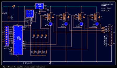
Stepper motors are widely used in applications such as process control, machine tools, and robotics. In particular, remote control of stepper motors is essential in robotics and process control. This document provides the circuit diagrams for both the transmitter...
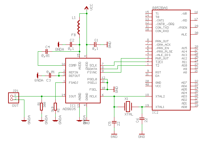
The AD9835 is a Direct Digital Synthesis (DDS) chip manufactured by Analog Devices. It comprises a phase accumulator, a sine wave table, and a 10-bit digital-to-analog converter (DAC). This chip can be utilized for both phase and frequency modulation...