
Basics 06 Mod

In the context of an amplitude modulation (AM) transmitter design, the key components include the RF power amplifier, modulator, and audio power amplifier. The RF power amplifier is responsible for generating the carrier wave, while the modulator introduces the audio signal to achieve modulation. The modulation process typically employs a transformer to couple the audio signal into the RF amplifier's plate circuit, ensuring that the audio frequencies are effectively superimposed onto the carrier wave.
The modulation depth is crucial, as it determines the extent of variation in the RF output voltage in response to the audio input. At 100% modulation, the output voltage swings between 0 and twice the high voltage, thereby creating sidebands that carry the audio information. The sidebands are critical for transmission, as they contain the actual audio content that is intended for reception.
In practical applications, the design must account for the frequency response of the audio signal and the characteristics of the RF amplifier to ensure efficient transmission. Additionally, the antenna matching network must be optimized to allow for effective radiation of the modulated signal while minimizing losses. The bandwidth of the transmitted signal is determined by the modulation frequency and the desired audio quality, which must be carefully balanced to meet regulatory standards for radio transmission.
Overall, the principles of AM transmission highlight the interplay between the carrier wave and the modulating audio signal, emphasizing the importance of both frequency and amplitude in successful radio communication.The very first form of radio communication was radio telegraphy, as opposed to wired telegraphy. The telegraph key turns the transmitter on when it is closed and off when open. The operator taps out the message in a long and short, dashes and dots, code and the person on the other end who knows the code reads the dots and dashes and translates the m into letters and then to words. I don`t know what year radios began to talk but the method was amplitude modulation (AM). Those early transmitters probably produced as much frequency modulation (FM) as they did AM but FM hadn`t been invented yet and there was no known way to detect it. So we will begin with AM. An unmodulated radio transmitter puts out a steady single frequency of constant amplitude. When it is amplitude modulated the voltage of the transmitter output is varied according to the modulating voltage.
The unmodulated transmitter output is called the carrier. As we will see when we study Single Sideband (SSB) this is a total misnomer. But never mind that, it`s universally called the carrier and that`s what we will call it. It was named that because the early radio engineers thought the steady RF signal carried the audio through the ether. Suppose we want to transmit a steady sine wave. That`s not very interesting to anyone who might be listening but who cares. We`re going to transmit it anyhow. The top wave in Figure 6. 1 shows an unmodulated carrier wave at the top, an audio sine wave second, and at the bottom, the carrier modulated by the audio wave.
This looks pretty straight forward. The audio wave is added to 1 to make it all above the axis and then it multiplies the carrier wave. If I didn`t need to go on to explain single sideband I could just leave it at that. But I am going on to SSB so we need to dig deeper into the AM signal. There is no difference between the theoretical operation of a mixer and a modulator. At low power the same circuit can be used for either one. As you will remember from your study of the All American 5 or the Simple Superhet a mixer creates sum and difference frequencies. So does a modulator. At power levels from about 5 watts to 5000 watts the modulation is done in the last, highest power, stage.
A specially made transformer couples the audio from an audio power amplifier into the plate circuit of the RF power amplifier as shown in Figure 6. 2 below. When there is no audio signal the DC voltage at the plate of the RF tube is equal to the HV (high voltage).
When audio is applied at 100% modulation the plate voltage varies from 0 to twice the HV value. This causes the RF voltage to vary from 0 to twice the no modulation value. If the RF tube is a pentode the screen grid has to be modulated along with the plate. If you want to build an AM transmitter don`t follow this plan. I made it up as I went along. It is meant to illustrate the principle not to be a construction project. Suppose we want to modulate a 100 kc carrier with a 6 kc audio wave. The modulator will pass the original frequencies through but will create two new frequencies, 94 kc and 106 kc. For 100 percent modulation, the condition shown in Figure 6. 1, the new frequencies will be one half the amplitude of the carrier. These new frequencies are called sidebands. Although the audio, 6 kc, may be present, the tuned circuits in the antenna matching network, the antenna its self, and the nature of propagation of radio waves will not allow the 6 kc audio to be picked up by a distant receiver so we will neglect that frequency from now on.
Sidebands are the new frequencies that are created on either side of the carrier wave. For example a radio station operating on 650 kc and transmitting an audio bandwidth of 50 cycles to 10 thousand cycles will have the carrier at 650, 000 cycles and an upper sideband extending from 650, 050 to 660, 000 cycles, and a lower sideband extending from 649, 950 to 640, 000 cycles. It should b 🔗 External reference
Related Circuits
A circuit designed to extract and measure the modulated carrier of an infrared remote control. This circuit amplifies the entire received signal, allowing the waveform to be displayed on an oscilloscope or a frequency counter. It can measure modulation...
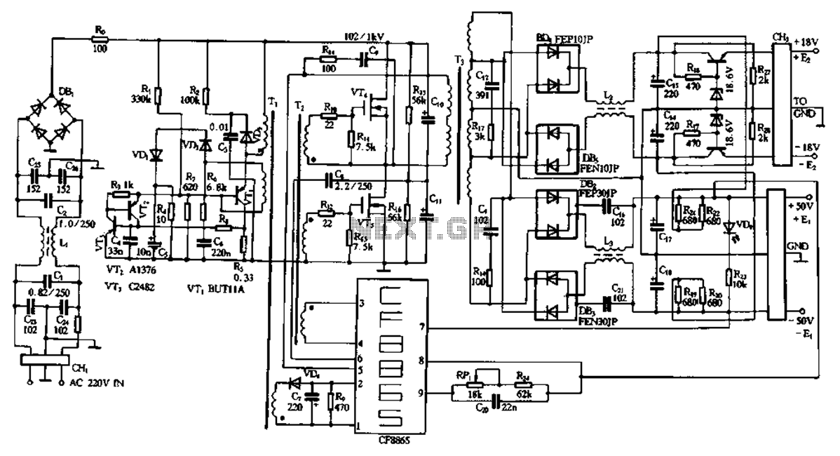
This document describes a specific module utilizing the CF8865 switching power supply circuit, which employs the integrated control module CF8865. In the figure, transistors VT4 and VTs are controlled by the excitation transformer Tz. The output is processed through...
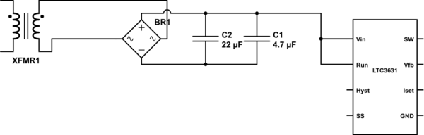
The leads from the transformer to the circuit are quite long (>5m). The 110V side of the transformer has been switched off frequently, which likely caused a spike on the secondary (24V) side. The input pin of the LTC3631...
The standard circuit will display directly in Hz (1MHz max), and there is a separate on board divider that will allow you to display directly in KHz (approx 40MHz max). Because the display reads directly in Hz or KHz...
This page serves as documentation for the circuits built utilizing the Modular Signal System, initially documented by Gregg Fuhriman in Railmodel Journal and further detailed on the Free-mo.org website. This project involved designing and constructing a circuit board for...
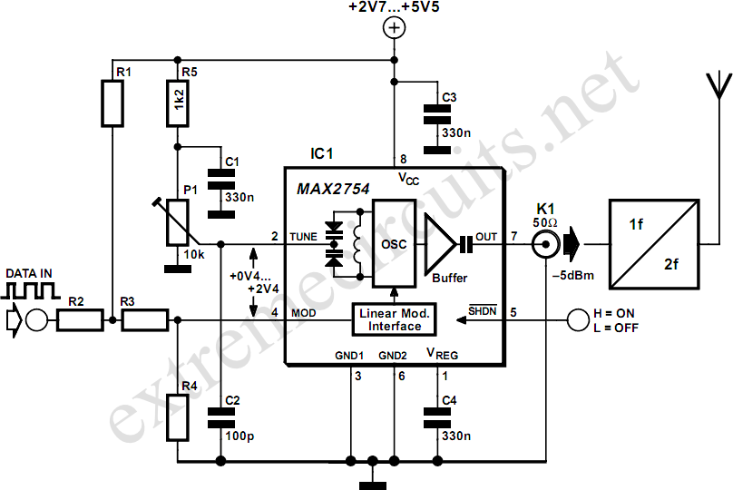
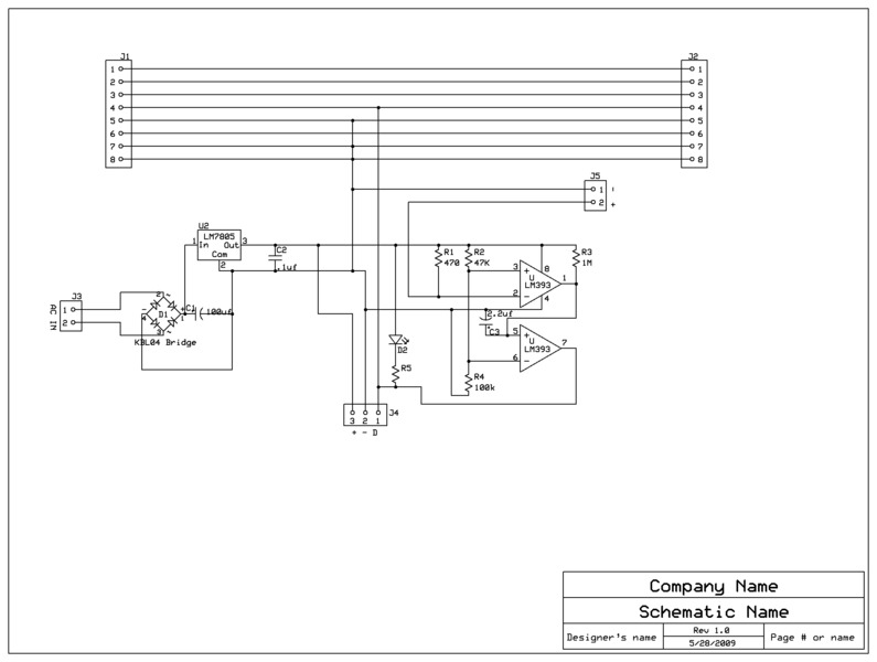
High-frequency voltage-controlled oscillators (VCOs) are challenging to construct, which is why Maxim has developed the integrated 1.2 GHz oscillator, the MAX2754. The center frequency is adjustable via the TUNE input, while a linear modulation input allows for frequency modulation....