
bass glow

The circuit utilizes an inverter designed to convert a low DC voltage from a battery into a higher AC voltage suitable for driving an electroluminescent (EL) sheet. The inverter circuit typically comprises key components such as a transformer, transistors or MOSFETs for switching, and capacitors for filtering. The design may include a feedback mechanism to stabilize the output voltage, ensuring consistent brightness of the EL sheet.
However, the noted higher-than-expected battery consumption suggests inefficiencies in the circuit. This could be due to factors such as inadequate component ratings, suboptimal switching frequencies, or insufficient power management techniques. It is advisable to analyze the circuit layout for potential improvements, such as optimizing the transformer turns ratio or selecting low-loss components.
The provided video serves as a visual reference for the inverter's operation, showcasing the EL sheet's illumination. Users interested in further enhancing the circuit's performance may consider integrating a more efficient power supply or exploring alternative inverter designs that reduce energy consumption while maintaining output quality.Since I used a ready-made inverter circuit to drive the EL sheet, this diagram is incomplete and also I`d say the battery consumption is much higher than it should be. As seen in the comments, an AVI video file is available without sound (as I used my webcam to record it).
If you are interested, you can download it from the address below. 🔗 External reference
Related Circuits
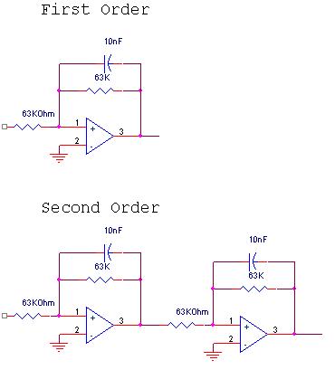
The circuit design involves a circular operational amplifier (op-amp) configuration that functions as a second-order low-pass and high-pass filter. The low-pass filter operates within a frequency range of 20 to 250 Hz, while details regarding the high-pass filter are...
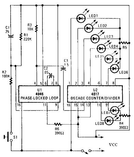
An electronic circuit for a roulette wheel can be constructed using a 4046 Phase-Locked Loop (PLL) that includes a Voltage Controlled Oscillator (VCO), two phase comparators, a source follower, and a Zener diode to generate a low-frequency pulsed output...
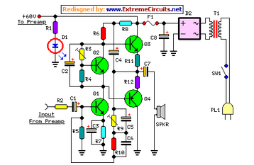
The circuit features low-cut and bass controls, with an output power of 40W into an 8 Ohm load and 60W into a 4 Ohm load. This design utilizes a well-established circuit topology for the power amplifier. The described circuit is...
Upgrading to a 3-prong AC cord is a common modification, as is the replacement of filter capacitors. Switching coupling capacitors to brands like Orange Drops or other boutique options is also popular, often enhancing the appeal in online auctions....
The following circuit illustrates a Bass-Treble Tone Control Circuit electronic diagram based on the LM1035N integrated circuit (IC). Features include a 0.3 Vrms input level, 80 dB signal noise ratio, 75 dB volume control, ±15 dB typical tone control,...
The LM1036 is a DC-controlled circuit designed for adjusting tone (bass/treble), volume, and balance in stereo applications such as car radios, televisions, and audio systems. It features an additional control input that enables straightforward loudness compensation. Four control inputs...