
Bass-treble Tone Control Circuit With LM1035N IC

The Bass-Treble Tone Control Circuit utilizing the LM1035N IC is designed to enhance audio signal processing by allowing users to adjust the bass and treble levels of the audio output. The IC provides a robust architecture that supports a variety of audio applications, ensuring high fidelity and minimal distortion.
The circuit operates with a specified input level of 0.3 Vrms, which is suitable for line-level audio signals. The signal-to-noise ratio of 80 dB indicates a high-quality audio output, minimizing unwanted noise during operation. The volume control feature, rated at 75 dB, allows for significant attenuation of the audio signal, providing flexibility in output levels.
Tone control is achieved through the use of variable resistors and capacitors, allowing users to modify the bass and treble frequencies by ±15 dB. This feature is critical for tailoring the audio output to suit personal preferences or specific acoustic environments. The circuit is designed to maintain a channel separation of 75 dB, ensuring that left and right audio channels remain distinct and clear, which is essential for stereo sound applications.
The power supply requirements for the circuit range from 9V to 16V, making it compatible with various power sources. The inclusion of passive components such as capacitors and resistors is vital for filtering and stabilizing the audio signals, while the switch allows for easy operation and control of the circuit.
Overall, this Bass-Treble Tone Control Circuit is a versatile and essential component in audio electronics, providing users with the ability to customize their listening experience effectively.The following circuit shows about Bass-treble Tone Control Circuit electronic circuit diagram. This circuit based on the LM1035N IC. Features: 0. 3 Vrms input level, 80 dB Signal noise, 75 dB volume control, ±15 dB typical Tone Control, 75 dB Channel separation, 9V to 16V supply voltage. Component: IC, Capacitor, Resistor, Switch. [f ree-circuits. com] Tags: Capacitor, circuit diagram, control circuit, control diagram, control schematic, electronic circuit, electronic control, IC, Resistor, schematic diagram, switch We aim to transmit more information by carrying articles. Please send us an E-mail to wanghuali@hqew. net within 15 days if we are involved in the problems of article content, copyright or other problems.
We will delete it soon. 🔗 External reference
Related Circuits
Originally posted by Pano: "Like putting milk and sugar in your coffee. Next time by, your Turkish coffee comes with no sugar, Dave." The provided text appears to be an informal comment comparing the addition of sugar and milk to...
The output voltage can be increased easily by placing a resistor in parallel with Ra until it reaches precisely 5.0 V. Switches S1 and S2 are preferably SPDT types with a center position, but three-way rotary switches can also...
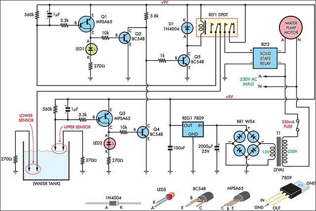
This circuit is designed to effectively fill a header tank for a reticulated water supply on a farm. It supports eight troughs located in various paddocks, where inadequate water supply can have serious repercussions for livestock. Previously, a timer-based...
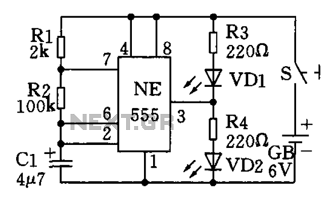
The circuit utilizes a 555 timer as the central component of a flashing light circuit. In normal operation, the light-emitting diodes (LEDs) VD1 and VD2 alternate flashing. The circuit comprises the NE555 timer, resistors R1 and R2, and capacitor...
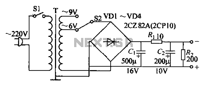
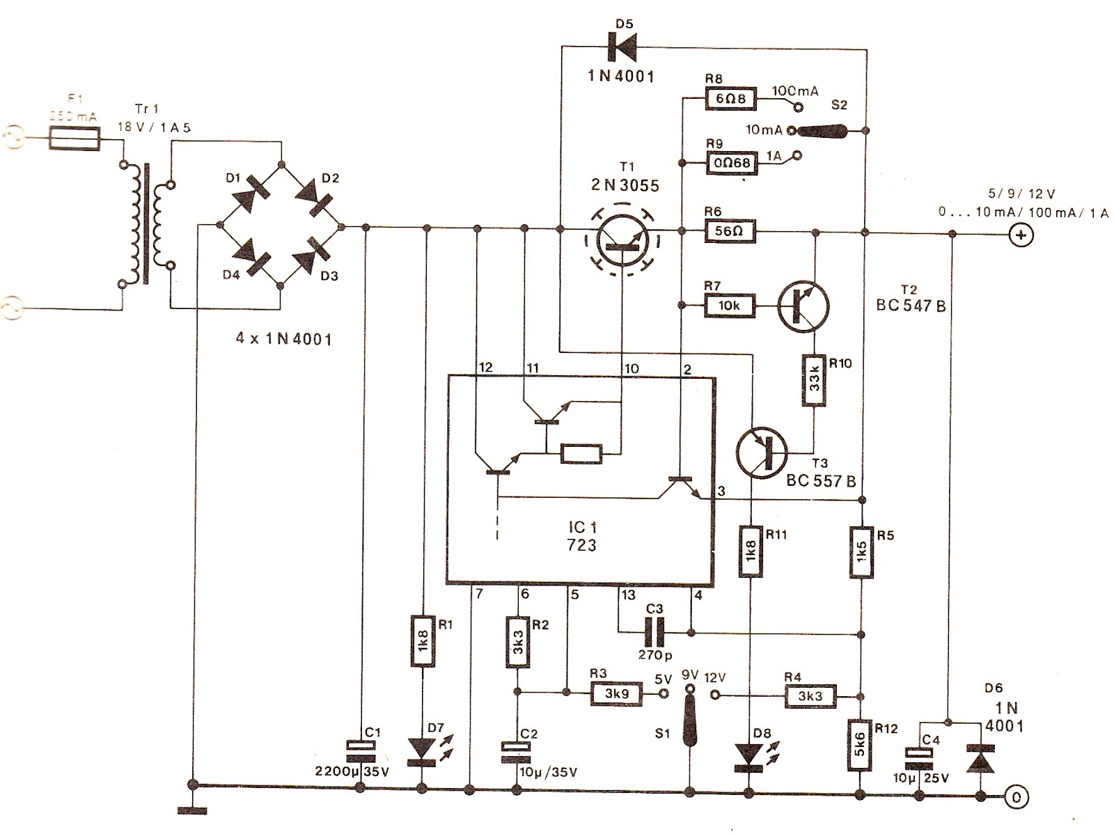
The adjustable current power supply circuit operates at 6V and 9V, utilizing a minimal number of components, which facilitates easy assembly. The circuit can deliver an adjustable output current of up to 100mA, serving as a suitable alternative to...
Converting periodic waveforms to square waves is essential for extracting clock signals from data, creating waveform generators, and developing timing-pulse generators. A square-wave conversion circuit is more advantageous when the duty cycle of the square wave is variable and...