
Bass Treble Loudness Tone Control Witha LM1036

The LM1036 integrates multiple audio control functionalities into a single chip, making it suitable for various audio systems. It operates using a DC voltage to adjust the audio characteristics, allowing for precise control over sound output. The circuit includes dedicated inputs for bass and treble adjustments, which enable users to enhance low and high-frequency sounds according to personal preferences or specific acoustic environments.
In addition to tone control, the LM1036 features a volume control mechanism that can be adjusted smoothly to provide a comfortable listening level. The balance control allows for the adjustment of audio levels between the left and right channels, ensuring an even sound distribution across stereo speakers. This is particularly important in stereo applications where sound localization and spatial audio presentation are critical.
The LM1036 is typically used in conjunction with external components, such as resistors and capacitors, to form a complete audio processing circuit. The chip's design facilitates easy integration into existing audio systems, and it is compatible with various power supply configurations, making it versatile for different applications.
Overall, the LM1036 is an essential component for enhancing audio quality in consumer electronics, providing users with the ability to tailor their listening experience effectively. Its compact design and efficient operation make it an attractive choice for audio engineers and designers looking to incorporate advanced audio control features into their products.LM1036 is a DC controlled tone (bass/treble), volume and balance circuit for stereo applications in car radio, TV and audio systems. Component: . 🔗 External reference
Related Circuits
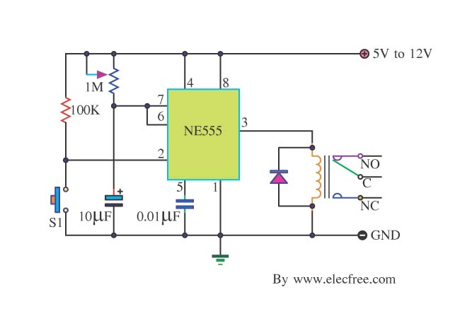
Many friends take an interest in the circuit involving the highly popular IC 555, which is an integrated circuit. This circuit sets the time in a basic manner. The IC 555 timer is a versatile and widely utilized component in...
The project described here is one that you can just build and have working straight away although it is entirely possible that you will want to experiment a bit, and requires only a small handful of parts. In its...
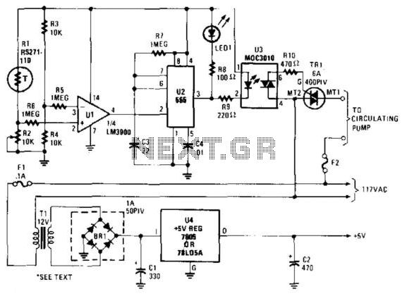
A thermistor (R1) is compared with a reference resistor (R2) in a Wheatstone bridge circuit. The output of comparator U1 goes high, which triggers U2. U2 introduces a delay of approximately 25 seconds. After 15 seconds, LED1 illuminates, U3...
This circuit can amplify music, sirens, or speech in response to increased ambient noise levels. It provides a solution for enabling a robot to effectively communicate in noisy environments. This circuit utilizes a sound detection mechanism to monitor ambient noise...
The primary motivation for utilizing battery power for trains is to eliminate the need for track cleaning and wiring. Track maintenance can pose significant challenges. Incorporating radio control into a battery-powered system enhances command control, an advantageous feature. In...
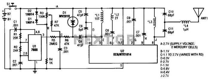
This transmitter can be utilized for multiple applications. An INS8048L microprocessor produces various codes based on keypad inputs. These codes are modulated onto a 40-kHz carrier frequency. Additionally, Q1 drives infrared LEDs LED1 and LED2. The transmitter circuit primarily consists...