
Remote Control Transmitter Circuit

The transmitter circuit primarily consists of the INS8048L microprocessor, which serves as the central processing unit. It interprets the signals from a keypad interface, generating specific codes that correspond to the keys pressed. The microprocessor is programmed to handle various functions, allowing for flexibility in application, such as remote controls or data transmission.
The generated codes are then modulated onto a 40-kHz carrier frequency, which is essential for efficient transmission of signals over infrared light. Modulation is crucial as it allows the codes to be embedded within the carrier wave, making them suitable for infrared communication.
The output stage of the transmitter includes two infrared light-emitting diodes (LEDs), LED1 and LED2, which are driven by a transistor Q1. This transistor acts as a switch, controlling the current flow to the LEDs based on the signals generated by the microprocessor. The use of two LEDs can enhance the transmission range and reliability, as they can work in tandem to emit a stronger infrared signal.
In summary, this transmitter circuit leverages the INS8048L microprocessor for code generation, employs modulation for effective signal transmission, and utilizes infrared LEDs to facilitate communication. This design is suitable for various applications requiring wireless data transmission through infrared signals. This transmitter can be used for a variety of purposes. An INS8048L microprocessor generates various codes depending on keypad presses. The codes are modulated on a 40-kHz carrier. Ql drives IR LEDs LED1 and LED2.
Related Circuits
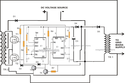
A single IC 556 has been utilized to generate PWM pulses. One half of the IC is configured as a high-frequency generator, which supplies the other half of the IC, set up as a pulse width modulator. The modulating...
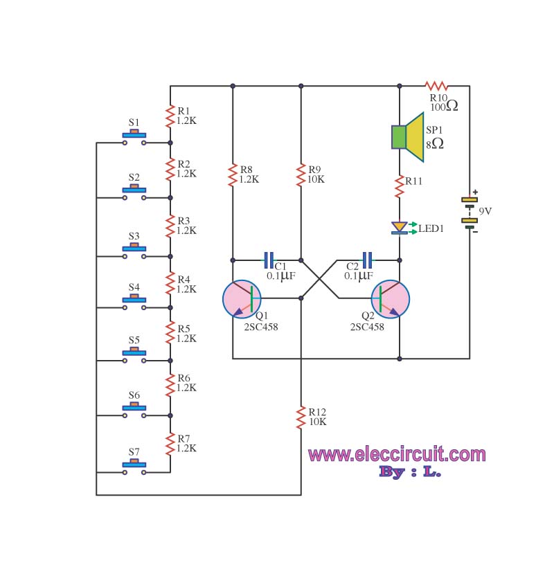
The circuit operates as an astable multivibrator, generating a square wave signal at a specific frequency. When powered, the circuit will function continuously. The astable multivibrator circuit is a type of oscillator that produces a continuous square wave output without...
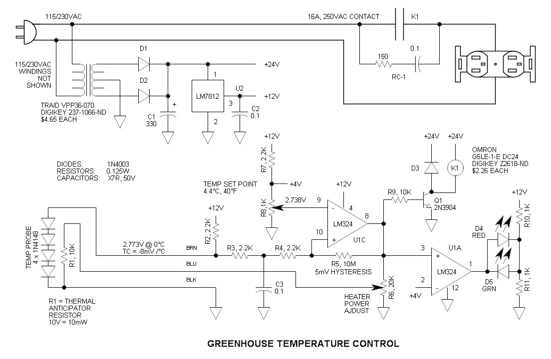
This circuit consists of four 1N4148 diodes connected in series with a thermal anticipation resistor (R1) heat-shrunk together at the end of a three-wire signal cable, which is visible in some photos. The thermal anticipation resistor is an old...

Is the battery empty, or is there something wrong with the device? This question often arises when troubleshooting a battery-powered device, such as a Walkman. When diagnosing issues with battery-powered devices, it is essential to systematically evaluate both the battery...
This is a transistor inverter circuit diagram rated for 100 watts, designed as an easy-to-build circuit. It utilizes only transistors and does not incorporate any integrated circuits. The circuit converts a 12V battery input to a 220V, 50Hz square...

This design circuit outlines a simple, low-cost, and ultra-compact VHF/UHF Low-Noise Amplifier (LNA) that can be implemented using the MAX2664 and MAX2665 devices, which are specifically tailored for VHF/UHF applications. The MAX2664 operates within the UHF frequency range of...