
Automatic Water Tank Filler Circuit

The circuit's design is crucial for ensuring a reliable water supply to livestock, particularly in environments where water levels fluctuate due to varying consumption patterns. The use of Darlington transistors allows for efficient switching, providing the necessary amplification to control the relay and pump system. The NOR gate configuration simplifies the logic required to manage the two sensors, ensuring that the pump operates only when needed. The choice of a solid-state relay for the pump control enhances durability and responsiveness, particularly under high inrush current conditions.
The sensors, constructed from stainless steel, are resistant to corrosion and can withstand the harsh environment typically found in agricultural settings. The careful placement of the sensors ensures that the system responds promptly to changes in water levels, preventing both overfilling and dry conditions that could jeopardize livestock health. The protective sealant used at the wiring junctions further enhances the reliability of the installation, safeguarding against moisture ingress that could lead to short circuits or failures.
Overall, this circuit exemplifies an effective solution for automated water management in agricultural applications, combining robust components and a straightforward control logic to maintain optimal water levels in the header tank.This circuit has been very useful in filling a header tank for a reticulated water supply on a farm. Eight troughs are supplied in different paddocks where a lack of water would have serious consequences for the stock. In the past, the tank had been filled daily by a time clock which was not successful. During hot weather, the stock would empty th e tank on a regular basis and then be without water for several hours or the tank would overflow and flood the area if the weather was wet and the cattle did not drink much. The circuit described has been used to maintain the level of water in the header tank within prescribed limits.
It controls a 3HP submersible bore pump which has a high starting current, necessitating a solid-state relay sufficient to take the starting load. Two Darlington transistors, Q1 & Q3, in conjunction with Q2 & Q4, are connected to the upper and lower water sensors in the tank.
Q2 & Q4 have a common 5. 6kO load resistor and function as a NOR gate. The output of the NOR gate drives Q5 which activates relay RLY1. Initially, when the water level is low, both sensors will be open-circuit, the NOR gate output will be high and the relay will be turned on. This causes the normally closed (NC) contacts of the relay to open and disconnect the lower sensor. However, the upper sensor will still be open circuit and the NOR gate output will be high, keeping the relay closed.
The normally open (NO) contact of the relay will be closed to operate the solid-state relay RLY2 to run the pump. This state continues until the water reaches the top sensor which will then drop the output from the NOR gate to 0V.
The disables relay RLY1 and the pump is stopped. In practice the upper level sensor is just below the overflow from the tank and the lower sensor about half way up the tank. The sensor contacts are simply two stainless steel screws about 25mm apart and screwed through the poly tank walls.
The wiring junctions on the side of the tank are protected by neutral-cure silicone sealant. 🔗 External reference
Related Circuits

This circuit is a simple telephone ringtone generator designed using minimal components. It produces a simulated telephone ringing tone and operates on a DC voltage ranging from 4.5V to 12V. This circuit can be utilized in standard intercom systems...
4V flat monitor high voltage power supply circuit diagram. A wide range of 7 to 40V to 5V DC-DC step-down circuit diagram. Light control switch circuit diagram for safety. Circuit 555 constitutes a control circuit diagram for photoelectric applications. The...
The three circuits were based on the vacuum tube ECC83, designed to produce phono preamplifiers in compliance with RIAA standards. The described circuits utilize the ECC83 vacuum tube, a dual-triode component known for its low noise and high gain characteristics,...
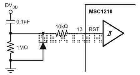
According to the MSC1210 datasheet, you will perform an external reset by taking RST pin high for two tOSC periods as this stops device operation, crystal oscillation, causes all digital pins to be pulled high from that point and...
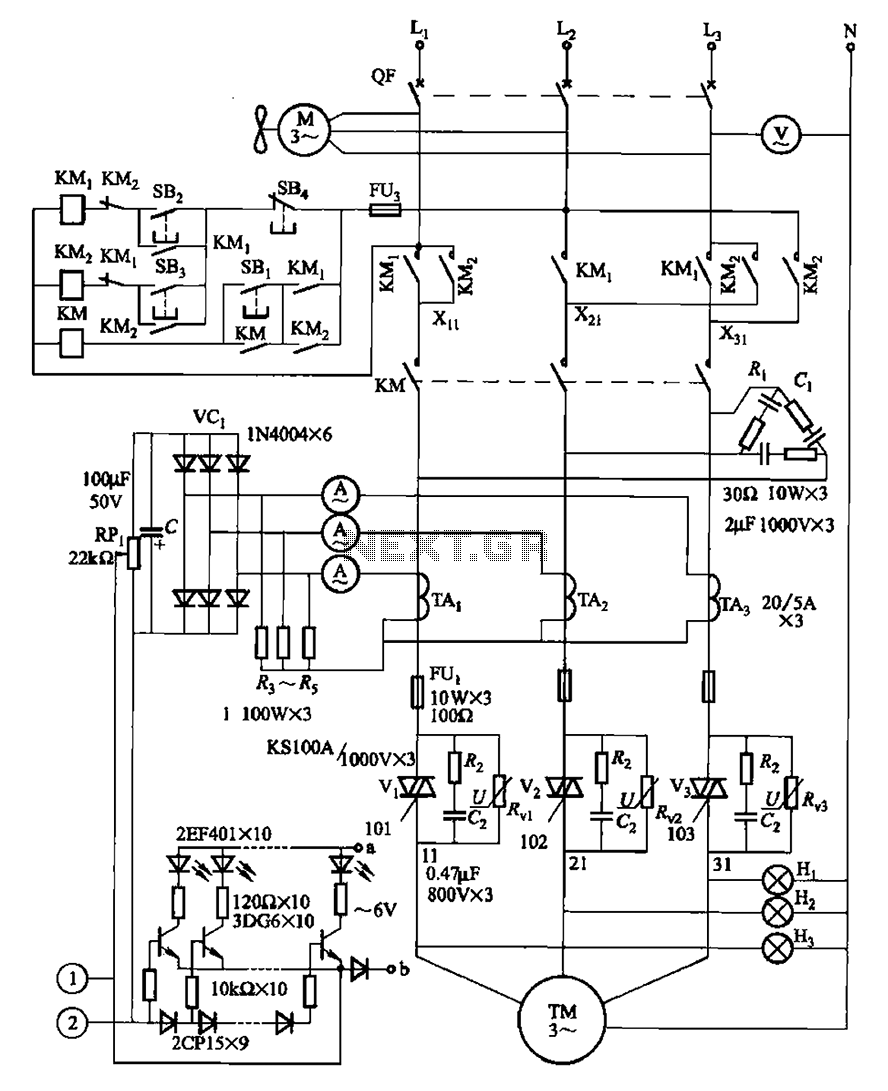
The circuit illustrated in Figure 3-178 is designed for controlling the speed and torque of a motor used in a continuous casting machine. It consists of the main circuit, a trigger circuit, and both manual and automatic control signal...
The individual expressed frustration while attempting to connect a circuit to a 15V supply, bypassing resistor R3 with a clip-on soldering heat sink. They noted that 555 timers emit a distinct odor when damaged. They have limited components remaining...