
battery backup circuit
The two-diode selector circuit is an efficient solution for applications requiring automatic switching between power sources while ensuring optimal performance and reliability. The use of Schottky diodes is advantageous due to their low forward voltage drop and rapid switching capabilities, which minimize power loss and enhance circuit responsiveness.
In this configuration, when the primary voltage source is present and exceeds the turn-on voltage of the diodes, the circuit allows current to flow through the selected diode, powering the load. If the primary source fails or drops below the necessary voltage, the second diode can take over, ensuring continuous power supply.
The inclusion of a PNP transistor in the circuit serves to manage the flow of current effectively, preventing reverse current from the load back into the power sources. The design also accounts for the voltage drop across the diodes, which is critical in low-voltage applications where even minor losses can impact performance.
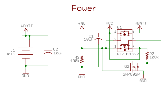
For applications that require flexibility in power source selection, the complementary FETs can be employed as an alternative to diodes. This approach can provide improved efficiency and is particularly suitable for higher power applications, although it necessitates careful consideration of the voltage levels between the power sources.
The schematic's power source switching section demonstrates a practical implementation of this concept, allowing the circuit to switch seamlessly between different voltage levels (e.g., +5V and +3V) based on availability. This feature is essential for devices like LCD backlight drivers, where consistent power supply is crucial for operation.
Overall, this two-diode selector circuit design is well-suited for applications requiring reliable power management with minimal losses, making it a valuable addition to low-power electronic systems.A 2 diode selector circuit if your primary voltage source is greater than the diodes turn on voltage and the input voltage of the second diode. Schottky diodes are recommended for both their low lower turn on voltage (typically 0. 4v) and high switching speed. You can use a 2 diode selector circuit if your primary voltage source is grea ter than the diodes turn on voltage and the input voltage of the second diode. Schottky diodes are recommended for both their low lower turn on voltage (typically 0. 4v) and high switching speed. Yes provided your voltages are all within the range the transistor can handle. I think the attached circuit would work. I`ve used something like this in a recent design and now the main and backup voltages can be equal. The transistor in the diagram is a PNP. Diodes have a voltage drop that needs to be accounted for. Another way to do it is with complementary FETs. A nice example is in the power source switching used here (the part of the schematic labeled "Power" which switches between +5v and +3v sources): Of course, the two weaknesses here are 1) these are low-power parts (intended for extremely low current device), and 2) it relies on the battery backup power source having a lower voltage than the external power source. Diodes have a voltage drop that needs to be accounted for. Another way to do it is with complementary FETs. A nice example is in the power source switching used here (the part of the schematic labeled "Power" which switches between +5v and +3v sources): Of course, the two weaknesses here are 1) these are low-power parts (intended for extremely low current device), and 2) it relies on the battery backup power source having a lower voltage than the external power source.
Left out a diode. Here is a circuit I`m using for switching between a battery and adapter (power pack to you aussies) for input to a lcd backlight driver. It employs a PNP mosfet to prevent current from being drawn from the battery when there is a voltage (provided by the adapter) present on the Gate.
🔗 External reference
Related Circuits
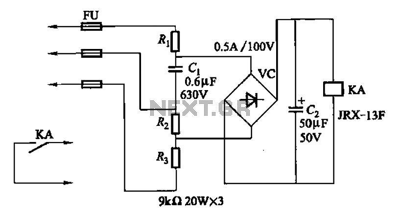
A capacitor C1 and resistors R1-R3 form a negative sequence voltage filtration device. The resistors and capacitors must meet the following requirements: R1, R2, R3 = 5.5/C1 (KN). The relationship between the resistance and capacitance values is arbitrary. Capacitor...
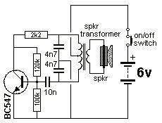
The Colpitts Oscillator is characterized by tapping the mid-point of the capacitive side of the oscillator section. The inductor can be the primary side of a speaker transformer. The feedback comes via the inductor. The Colpitts Oscillator is a type...

This design is for a charger circuit suitable for lead-acid batteries, including flooded, gel, and AGM types. The circuit features a simple design. The automatic function means that this charger will stop charging automatically when the battery voltage reaches...
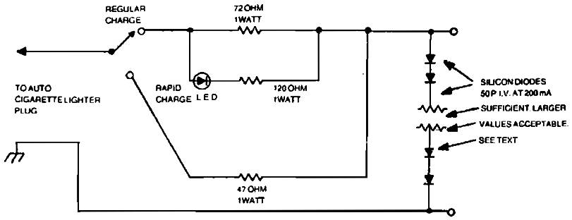
Car charger for NiCd battery packs power supply. This is a car NiCd battery charger circuit that can charge any Ni-Cd battery between 4.8 and 4.4 volts from a classic 12 volts car battery. The charging current is constant...
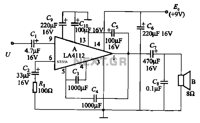
Audio power amplifier circuit utilizing the LA4112 integrated power amplifier along with additional components as shown in the figure. The audio power amplifier circuit based on the LA4112 integrated power amplifier is designed to deliver high-quality audio amplification for various...
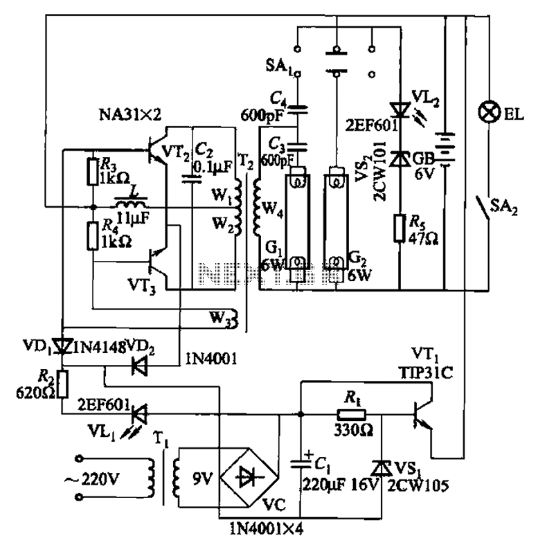
This is a Nissan Panasonic rechargeable emergency fluorescent lamp circuit. It features built-in 6V, 4Ah high-energy batteries that can be directly charged. The circuit supports two 6W fluorescent lamps. It includes functional switches SAi and SAz. When SAi is...
Warning: include(partials/cookie-banner.php): Failed to open stream: Permission denied in /var/www/html/nextgr/view-circuit.php on line 713
Warning: include(): Failed opening 'partials/cookie-banner.php' for inclusion (include_path='.:/usr/share/php') in /var/www/html/nextgr/view-circuit.php on line 713