
Simple Colpitts Oscillator circuit

The Colpitts Oscillator is a type of electronic oscillator that generates sine waves using a combination of inductors and capacitors. It is known for its simplicity and stability in frequency generation. The oscillator primarily consists of a tank circuit formed by an inductor (L) and two capacitors (C1 and C2) connected in series. The mid-point of the capacitive divider formed by C1 and C2 is where the output signal is taken, which is critical for determining the frequency of oscillation.
In this configuration, the feedback necessary for sustaining oscillations is provided through the inductor. The inductor may be implemented as the primary winding of a speaker transformer, which serves dual purposes: it provides the necessary inductance for the tank circuit and can also couple the generated signal to a load, such as a speaker or another circuit stage.
The frequency of oscillation (f) for a Colpitts Oscillator can be calculated using the formula:
f = (1 / (2π√(L * (C1 * C2) / (C1 + C2))))
This equation illustrates the relationship between the inductance and capacitance values in determining the output frequency. The choice of components significantly impacts the stability and performance of the oscillator. Proper biasing and component selection are essential to ensure reliable operation, especially in applications where frequency precision is critical.
The Colpitts Oscillator is widely used in various applications, including signal generation in RF circuits, clock generation in digital circuits, and as a local oscillator in communication systems. Its design can be adapted to suit different frequency ranges by selecting appropriate values for the inductor and capacitors, making it a versatile choice for engineers in the field of electronics.The Colpitts Oscillator is characterised by tapping the mid-point of the capacitive side of the oscillator section. The inductor can be the primary side of a speaker transformer. The feedback comes via the inductor.. 🔗 External reference
Related Circuits
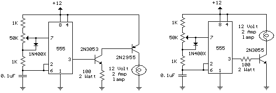
The schematic diagram illustrates a 12 Volt Car Lamp Dimmer Circuit Design utilizing a 555 Timer. This circuit can be employed to dim a standard 25-watt lamp. The 12 Volt Car Lamp Dimmer Circuit utilizes a 555 Timer in astable...
This simple circuit is designed to detect RF radiation leakage from transmitters, faulty connections, broken cables, or equipment with inadequate RF shielding. It is specifically tailored for the 2-meter amateur radio band (144-146 MHz in Europe). The device features...
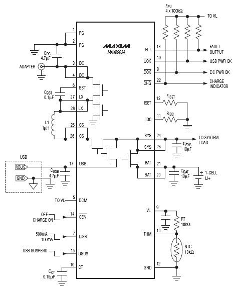
The DC input for this charger IC operates from 4.15V to 16V with a maximum protection limit of 20V. In contrast, the USB input has a voltage range of 4.1V to 6.3V, with protection up to 8V. The charger integrated...
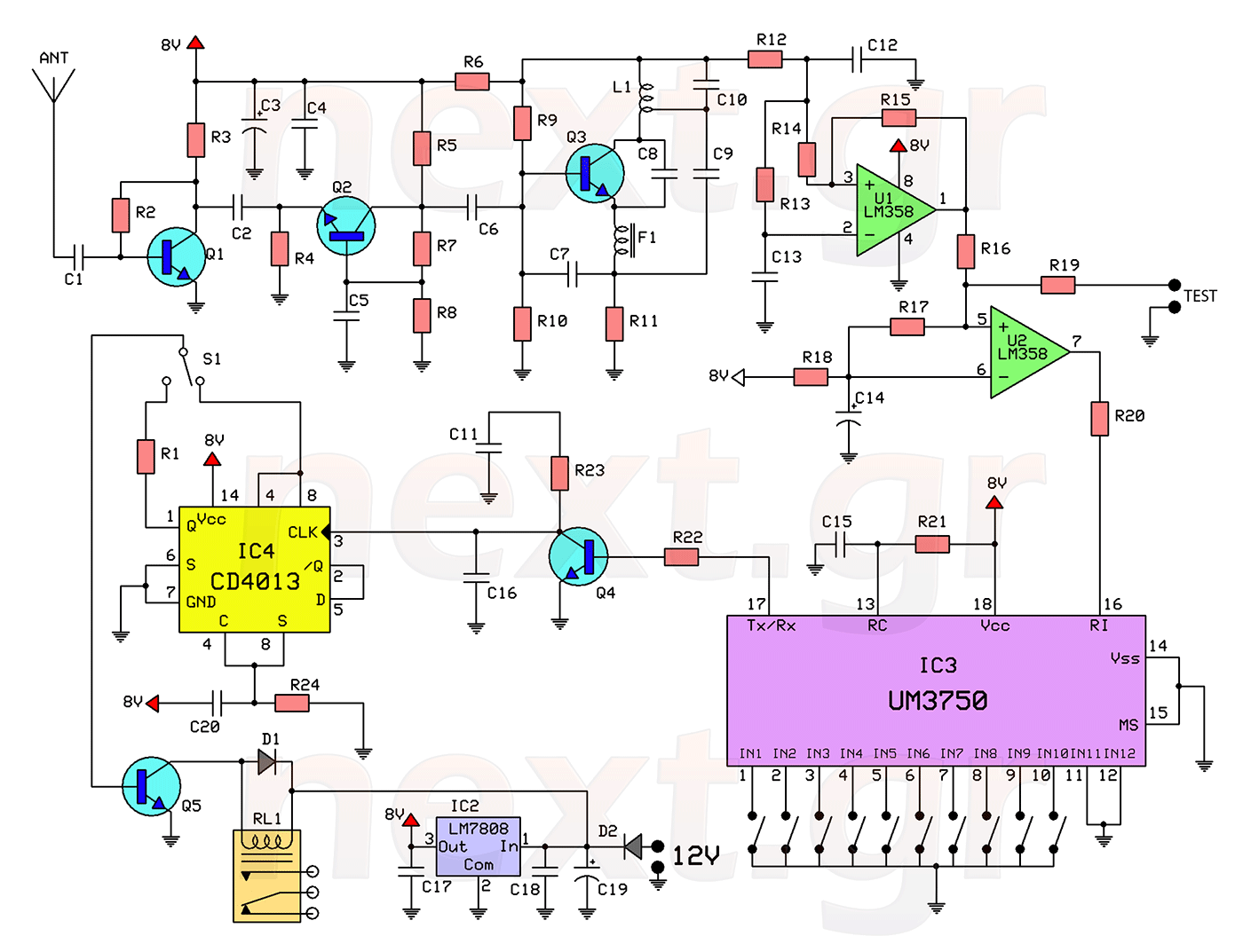
This circuit includes a 2048 radio remote control transmitter and a corresponding wireless receiver that features high reception sensitivity and low power consumption. The combination of these two components provides a highly reliable remote control system, suitable for various...
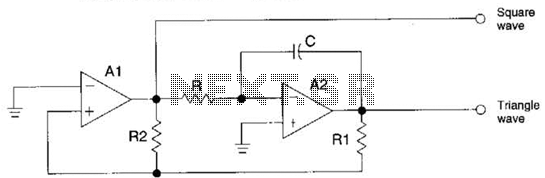
The circuit generates precision triangle and square waves. The output amplitude of the square wave is determined by the output swing of operational amplifier A1, while the ratio of resistors R1 to R2 sets the amplitude of the triangle...
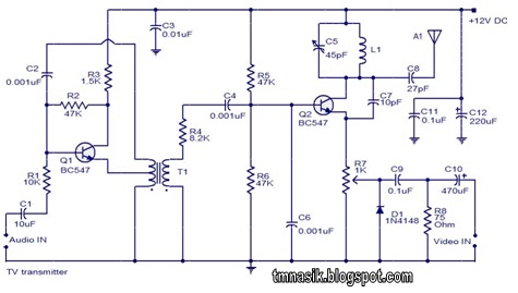
The TV transmitter circuit described utilizes UK standard 1 FM modulation for audio and PAL modulation for video. The audio signal intended for modulation is first amplified using transistor Q1 and its associated components. Transistor Q2 serves dual purposes:...