
Battery Monitor Circuit

The battery monitor circuit typically consists of a voltage divider, an operational amplifier (op-amp), and a display unit, such as an LED or an LCD. The voltage divider is used to scale down the battery voltage to a level that is safe for the op-amp input. This ensures that the op-amp can accurately process the voltage without being damaged by excessive voltage levels.
The op-amp is configured as a comparator, which compares the scaled voltage from the voltage divider against a reference voltage. This reference voltage can be set using a precision voltage reference or another voltage divider connected to a stable power source. When the battery voltage falls below a certain threshold, the op-amp output changes state, triggering the display unit to indicate that the battery is undercharged.
The display unit can be configured to show the battery voltage level in real-time or provide a simple indicator (such as a green LED for adequate charge and a red LED for low charge). In more advanced designs, a microcontroller can be incorporated to provide additional features such as data logging, alarms, and even communication with other devices.
Power for the circuit can be derived directly from the battery being monitored or through a separate power supply. It is crucial to ensure that all components are rated for the maximum expected battery voltage to prevent damage and ensure reliable operation. Proper PCB layout and component selection are also essential to minimize noise and improve the accuracy of the voltage readings.
In summary, this battery monitor circuit serves a vital role in maintaining the health of a 12-volt lead-acid battery by providing a simple yet effective means of monitoring its charge level, thereby extending its operational life.Here is a simple Battery Monitor circuit for a quick check of 12 volt Lead-Acid Battery. Battery charge should be constantly monitored to increase the life.. 🔗 External reference
Related Circuits

The Pyro Propeller Clock POV schematic is relatively straightforward. It consists of three primary components: the power supply utilizing a 7805 voltage regulator, the LED output control managed by a PIC18F252 microcontroller and a 74LS373 latch, and the 'home'...
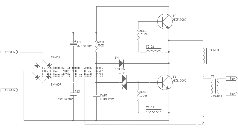
A small (2 to 3 meters) neon electronic transformer circuit diagram is provided below. The described circuit diagram is intended for use with neon lighting systems, specifically those requiring a transformer to operate efficiently within a range of 2 to...
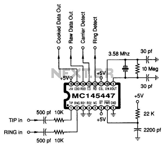
This circuit dials a stored DTMF tone sequence from an EPROM when a control line is taken to 0 V. IC1 is a Schmitt trigger oscillator, operating at approximately 2 Hz. It clocks a 4024 binary counter. The outputs...
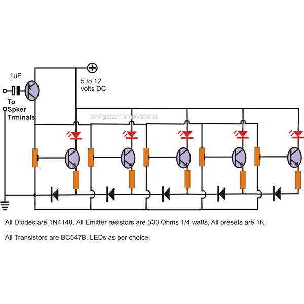
The LEDs in the circuit light up sequentially and "dance" in response to the music level applied at the input, preferably from the speaker terminals of the audio device being monitored. This configuration is consistent across all LEDs in...
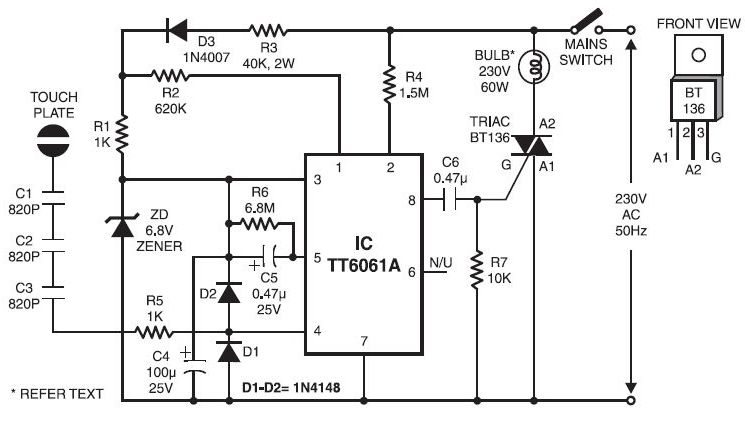
Typically, when a car door is closed, the dome light turns off immediately. This circuit allows the dome light to gradually fade in brightness before eventually turning off. An electronic transformer dims halogen lamps and is a straightforward device...
This 2-meter 144 MHz fox hunt transmitter is utilized in amateur competitions where participants seek to locate a concealed transmitter using primarily homebrewed receivers. The 144 MHz fox hunt transmitter is designed for use in amateur radio competitions, commonly referred...