
Neon transformer circuit diagram

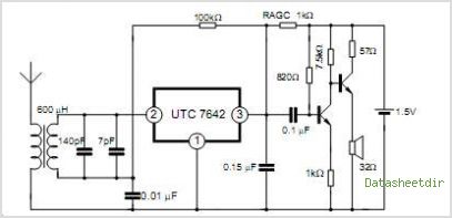
The described circuit diagram is intended for use with neon lighting systems, specifically those requiring a transformer to operate efficiently within a range of 2 to 3 meters. The electronic transformer serves to convert standard line voltage (typically 120V AC or 240V AC) to a lower voltage suitable for neon tubes, generally around 12V to 15V AC.
In the schematic, the primary components include the transformer itself, which is designed to handle the required load while maintaining the necessary output voltage. The circuit may also include a rectifier to convert the AC output to DC if the neon tubes require a direct current for operation, although most neon lights operate efficiently on AC.
Additional components in the circuit may consist of capacitors for filtering, ensuring a stable output voltage, and resistors for current limiting to protect the neon tubes from overcurrent conditions. An optional fuse can be incorporated for safety, preventing overcurrent situations that could lead to circuit failure or damage to the neon lights.
For effective operation, the transformer must be rated appropriately for the total wattage of the neon tubes being used. The layout of the circuit should ensure minimal distance between the transformer and the neon tubes to reduce voltage drop and maintain performance. Proper insulation and housing of the transformer and connections are also critical to ensure safety and reliability in operation.
This circuit is suitable for various applications including decorative lighting, signage, and architectural illumination, where neon lighting is desired for its distinctive glow and visual appeal.Small (2 to 3 meters) of neon electronic transformer circuit diagram as follows:
Related Circuits
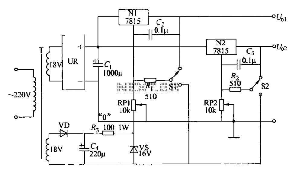
An adjustable dual voltage power supply circuit is presented, suitable for frequent experimental use. The current output does not exceed 1A, and both voltage outputs are adjustable. The circuit utilizes N1, N2, and 78 series three-terminal voltage regulator integrated...
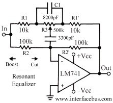
This topic discusses a resonant equalizer, which is a distinct type of circuit compared to the standard audio equalizer, although both achieve similar outcomes. The key difference is that the frequency responses of both the high and low frequency...
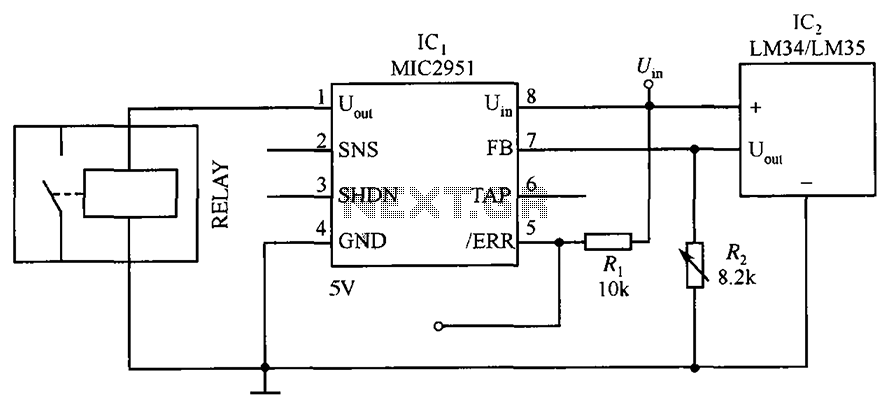
The circuit depicted in the figure utilizes a thermal protection system featuring the MIC2951 component. The temperature threshold can be adjusted by modifying resistor R2. The thermal protection circuit employing the MIC2951 is designed to monitor and regulate temperature within...
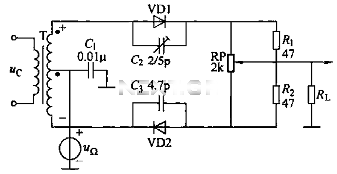
A common diode balanced modulator circuit is illustrated. It comprises two identical performance diodes and a center-tapped transformer configuration. The diodes used are VD1 and VD2, specifically 2AP9 models. The parameters for the circuit elements are detailed in FIG....
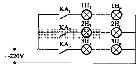
The relay control system utilizes multiple pairs of contacts, allowing for the connection of higher power lamps in parallel. The circuit design is straightforward; by altering the capacitance of the capacitor, different flashing frequencies can be achieved. The described circuit...
A low-cost vacuum cleaner system based on the P89LPC901 is introduced in this application note. The design hardware and software are thoroughly discussed. This system can also guide the design of other universal motor driving systems that require robust...