
Mains Operated LED Circuit Schematic

This LED circuit utilizes a few essential components to achieve efficient operation from a high-voltage AC source. The fundamental components include a bridge rectifier, a current-limiting resistor, and an LED or an array of LEDs.
The circuit begins with the AC mains input, which is connected to a bridge rectifier. The bridge rectifier consists of four diodes arranged in a specific configuration to convert the AC voltage into a pulsating DC voltage. This conversion is crucial as LEDs require a direct current (DC) to function properly.
Following the rectification process, a smoothing capacitor may be added to reduce the ripple in the output voltage, providing a more stable DC supply to the LEDs. The value of this capacitor should be chosen based on the load current and the desired ripple voltage.
To limit the current flowing through the LEDs, a current-limiting resistor is included in series with the LED. The resistor value can be calculated using Ohm's law, taking into account the forward voltage drop of the LED and the desired operating current. It is essential to select a resistor with an appropriate power rating to prevent overheating.
The LED or LED array is connected in parallel with the current-limiting resistor. Depending on the application, multiple LEDs can be connected in series or parallel to achieve the desired brightness and color output.
This circuit design is advantageous due to its simplicity and effectiveness in converting high-voltage AC power into usable light, making it suitable for various lighting applications where space is limited, yet high efficiency is required. Proper heat dissipation measures should also be considered to ensure the longevity of the components used in the circuit.Small in size! Big in use Here is a simple and powerful LED circuit that can be operated directly from the AC 100 volt to AC 230 Volts mains supply. The c.. 🔗 External reference
Related Circuits
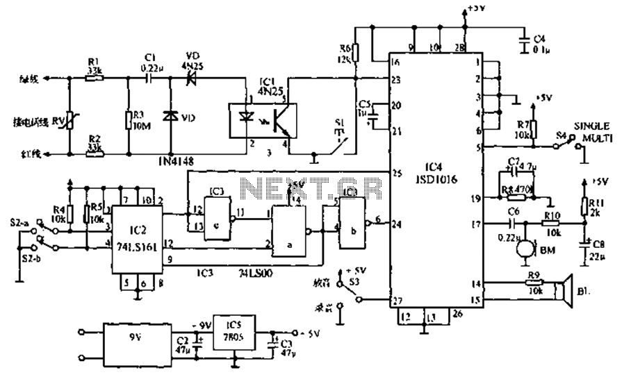
The call is made using the ISD1016 language chip for voice generation instead of a traditional phone ringing message controller schematic circuit. This controller can store messages, music, songs, or other sounds, serving as an alternative to monotonous ringing. The...
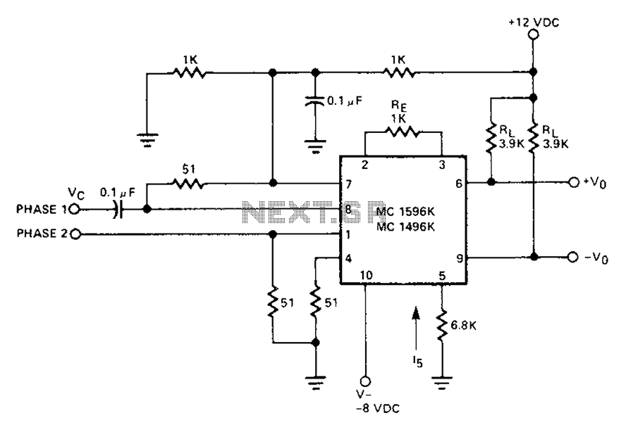
The circuit involves a Signetic balance modem connection utilizing a transistor array as a phase detector. It provides information about the cosine of the phase angle, which corresponds to the frequency of the input signal combined with the integrated...
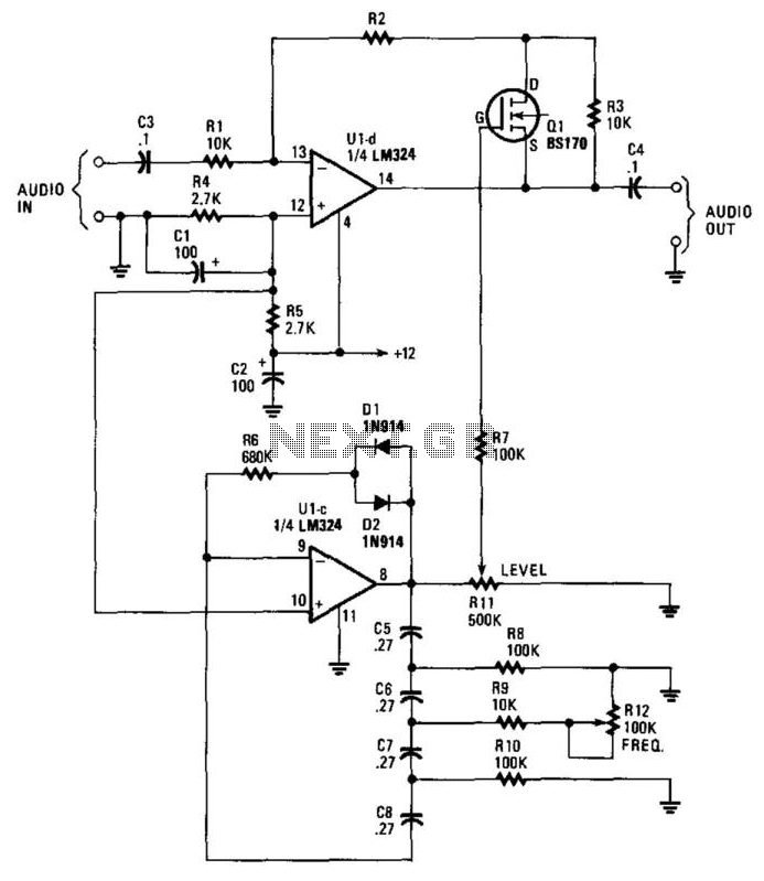
This circuit incorporates a Very Low Frequency (VLF) Amplitude Modulation (AM) component into an audio signal. This effect is commonly utilized in musical instruments. U1C, a phase-shift oscillator functioning at a few Hertz, generates a signal that modulates the...
This unit captures the ATV signal by sampling the transmission line with minimal insertion loss. It features two N connectors for input and output connections, and a BNC connector is utilized for the video output. The detected output is...
The circuit utilizes a 4-bit encoder to generate data, which is then modulated using an RF modulator for transmission. On the receiving end, the signal is demodulated, and a decoder retrieves the 4-bit data. The pin configuration for the...
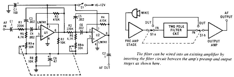
This variable-frequency audio bandpass filter is constructed using two 741 operational amplifiers connected in cascade. The two 741 op amps are configured as identical RC active filters and are cascaded to enhance selectivity. The filter's tuning range spans from...