
Battery Powered Tube Regenerative Receiver

A schematic for this regenerative receiver design would include key components such as the tuning capacitor, variable resistor, and audio frequency amplifier. The layout should clearly depict the mechanical mounting of the tuning mechanism and the variable capacitor, ensuring that both components are securely fixed to minimize movement. The coil would be represented with taps for frequency selection, and the placement of Molex connectors should be illustrated to show their connection to the coil. The crystal socket should be depicted at the tuning capacitor, with options for a jumper or capacitor to adjust the tuning capacitance. The audio output transformer should be included in the schematic, along with the potentiometer for signal adjustment. The circuit should also show the B+ supply connection and the audio frequency choke, with notes indicating the measured plate current and the decision to use resistance coupling. Additionally, provisions for future RF stage integration should be noted in the layout. Overall, the schematic will provide a clear and comprehensive representation of the regenerative receiver design, highlighting the critical components and their interconnections to facilitate understanding and implementation.Basic Regen design is pretty common, so BEFORE the schematic comes the "concept stage", the "what`s available in the junkbox stage", back to the "concept stage", followed by the "mechanical/electrical layout stage", then sketch a rough schematic. and do it all over again. The BC-221 has always impressed me as having about the simplest, smoothest, no backlash, tuning mechanism which is readily available to us. In fact, I picked up another two beat up BC-221 derivatives (forgot the numbers) at the last swapfest, one for $5 and one for $7. can`t beat that for really good parts including the covers. This is a Regen and all Regens should be breadboarded on a piece of plywood (personal opinion based on my first experience).
An 8" x 9" breadboard looks about right and will fit inside the diagonally cut covers of and old BC-221 derivative (see the picture). The tuning mechanism and variable were mounted on the "front" panel and the panel was reinforced with extra ribs to reduce flexing.
Having both the tuner mechanism and the variable capacitor on the same panel prevents additional movement. Selection of a good "solid" coupler and alignment of the 2 shafts is important. If you use shims, you still need solid mechanical mounting and aluminum is easy to work. After measuring the coil with my invaluable AADE L/C Meter and doing a little figuring, the coil I had picked out should cover the desired frequency range with 4 taps and a smaller value tuning capacitor for the higher frequencies.
Molex connectors were chosen for the taps because they are a good connection (better than a clip), cheap, and provide the shortest lead length. The coil was located to give the tuning capacitor plenty of room and to allow for installing a shield if necessary.
The antenna and ground connections originate in the same area to maintain short lead lengths. In order to lower the tuning capacitance, a crystal socket was installed at the tuning capacitor. That socket accepts a crystal base with either a jumper or 100pf SM capacitor to lower the effective tuning capacitance from 256pf to 72pf. Unused crystal bases are stuck to a magnet on the audio output transformer in the middle of the board to prevent loss.
EVERYTHING on a Regen is affected by capacitance and at these "direct conversion" receiver frequencies and the extreme Regen gain, it does not take much capacitance to "tune" the set. Spent quite some time looking for an ideal AF choke to put in the B+ lead of the Regen section to "increase the 27V B+" to that tube vs resistance coupled.
I tried a relay coil which had a 25H inductance (good) but the overall response in the audio frequency range fell off sharply after 1000Hz. An output transformer primary had only 5H max (not enough). Then I measured the plate current on that stage. it was only 30uA. That means a VERY small DC voltage drop, so I went back to the resistance coupled approach (no AF distortion with a resistor either).
Since the Regen plate current is so low, plate resistances of 100K are no problem. Installed a 1M potentiometer and found that the signal "peaks" at about 300K with 36V B+. This peak supplies the optimum AF voltage to the AF amplifier. Another useful control. Decided against an RF stage for isolation due to the extremely small antenna coupling capacitor used, but have left physical room in the event I need it later. Using two AF stages, which I assumed would be needed if B+ was 27V, was not required. Even with an impedance mismatch between the 2nd AF stage and the headphones, volume was excessive. A single stage AF power amplifier with an output transformer is more than adequate. Toyed with just a single 1T4 tube regen, but the volume is lacking (plate current 30uA) and you really want to isolate the headphone drive from the Regen section.
I understand now that the throttle cap is not for decreasing tickler effectiveness by bypassing the signal to ground, it`s for fee 🔗 External reference
Related Circuits
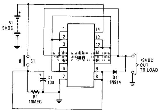
This battery saver circuit can automatically turn off a small piece of test equipment after a desired period of time, allowing for worry-free operation in a workshop environment. The circuit utilizes a CD4011 integrated circuit (IC) to function as...
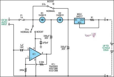
This circuit is designed to charge between one and twelve NiCd cells using a car battery. When switch S1 is in the "normal" position, it can charge up to six cells. The LM317 regulator functions as a simple current...
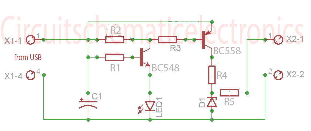
Without a USB to phone battery charger circuit, charging a phone battery using a USB port on a computer can quickly damage the battery, resulting in bulging. This occurs because the voltage output from USB is 5 volts, while...
This website was developed to assist students in discovering ideas for their projects or final year projects (FYP). All content presented here is sourced from reliable blogs, websites, and forums. The owner of this website assumes no responsibility for...
Most telephone equipment today utilizes a DTMF receiver integrated circuit (IC). A widely used DTMF receiver IC is the Motorola MT8870, which consists of 18 pins and is employed in telephones and various other applications. When projects utilizing this...
The circuit is conceptually similar to the BK Butler/Tubeworks Tube Driver. Operating on a 9V supply, the tubes function in "starved plate" mode, as preamp tubes typically require 100V-300V. This situation is akin to utilizing a Variac on a...