
Battery Saver Circuit Circuit

The described battery saver circuit is designed to enhance the efficiency of small test equipment by ensuring that power is conserved when the equipment is not in use. The core component, the CD4011 IC, is a quad 2-input NAND gate that can be configured in various ways to create different logic functions. In this application, one of the NAND gates is used in conjunction with a resistor-capacitor (RC) network to create a timing function.
The RC network consists of a resistor (R1) and a capacitor (C1) connected in series. When power is applied to the circuit, C1 begins to charge through R1. The time constant of the circuit, which determines how quickly C1 charges, is given by the product of R1 and C1 (τ = R1 × C1). Once C1 reaches a certain voltage threshold, the output at pin 7 of the CD4011 goes low. This low output causes the other three NAND gates to hold their outputs high, maintaining a 9-V supply to the connected test equipment.
After approximately 10 minutes of operation, the voltage across C1 drops sufficiently to cause the output at pin 7 to transition low. This effectively cuts off the power supply to the test equipment, preventing unnecessary battery drain. The circuit can be reset by momentarily closing switch S1, which discharges C1 and allows the circuit to begin the timing cycle anew.
This battery saver circuit is particularly useful in scenarios where test equipment may be inadvertently left on, ensuring that batteries are preserved and extending the life of the equipment. The simplicity and reliability of the CD4011 IC, along with the straightforward RC timing method, make this circuit an effective solution for battery management in portable electronic devices. This battery saver circuit can automatically turn off a small piece of test equipment after a desired period of time, allowing you to leave your shop worry free.This circuit uses a CD4011IC to act as a simple timer. One section acts as an RC discharge timer (pin 7). This causes ils output to go low, holding the three other outputs high acting as a 9-V source. After Cl/Rl discharges approximately 10 minutes, the output drops to zero. SI resets the circuit.
Related Circuits
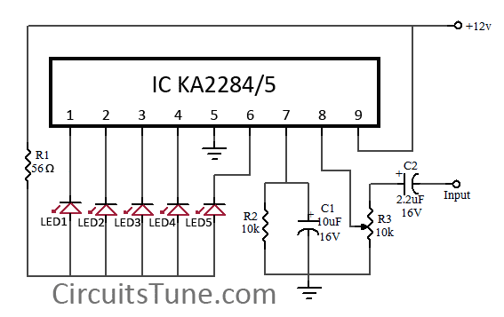
This is a simple circuit diagram of a 5-LED audio VU meter utilizing the ICs KA2284 or KA2285. The KA2284 and KA2285 are monolithic integrated circuits designed as logarithmic display driver ICs. They serve as bar-type display drivers for...
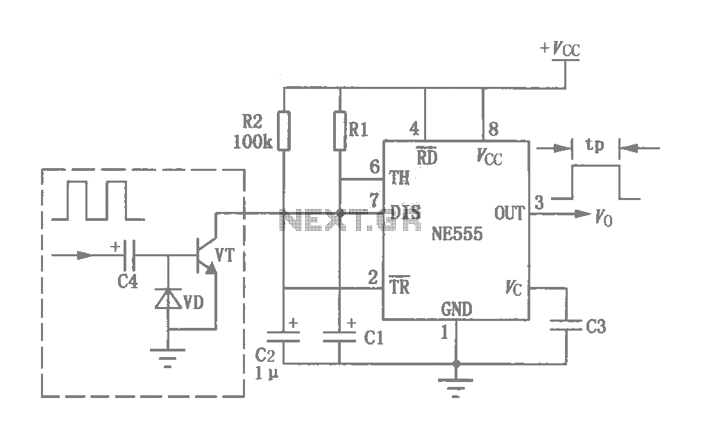
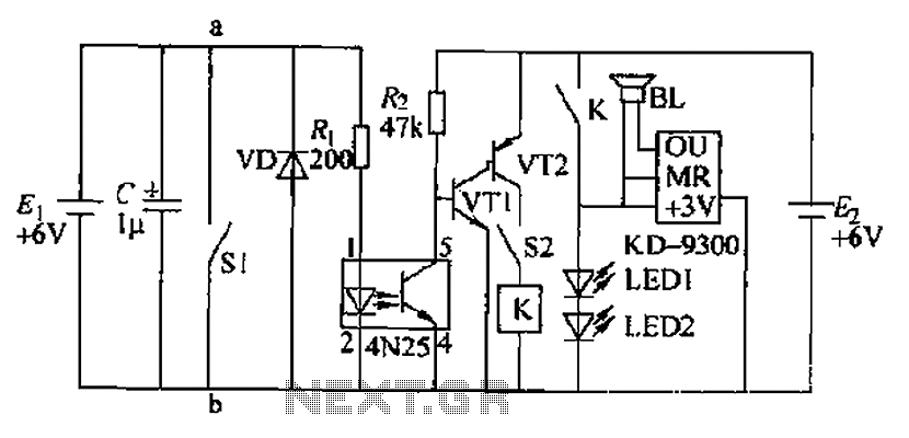
This circuit was originally a type of power-delay control circuit, where the delay time is determined by the timing elements R1 and C1. Additionally, with the inclusion of a "watchdog" circuit, it can be utilized as a monitoring circuit...
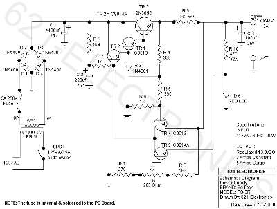
The following circuit illustrates the SciTech PS-3R Power Supply Circuit. Features include 13.8V DC output, 5 Amps surge capability, and a constant output of 3 Amps. Components include a transistor and others. The SciTech PS-3R Power Supply Circuit is designed...
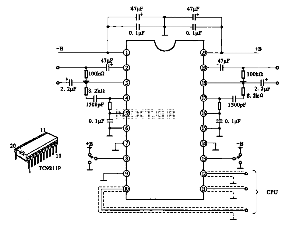
A typical electronic volume control circuit is commonly used in stereo audio devices connected through a computer (CPU). The circuit adjusts the volume of stereo signals via input and output pins. Control signals are sent to the CPU (including...
Due to the fast pace of modern life, intense competition, and widespread insomnia, which poses health risks, this section presents a feasible and effective method for controlling photoelectric hypnotic music to alleviate insomnia and facilitate sleep. The principle circuit...
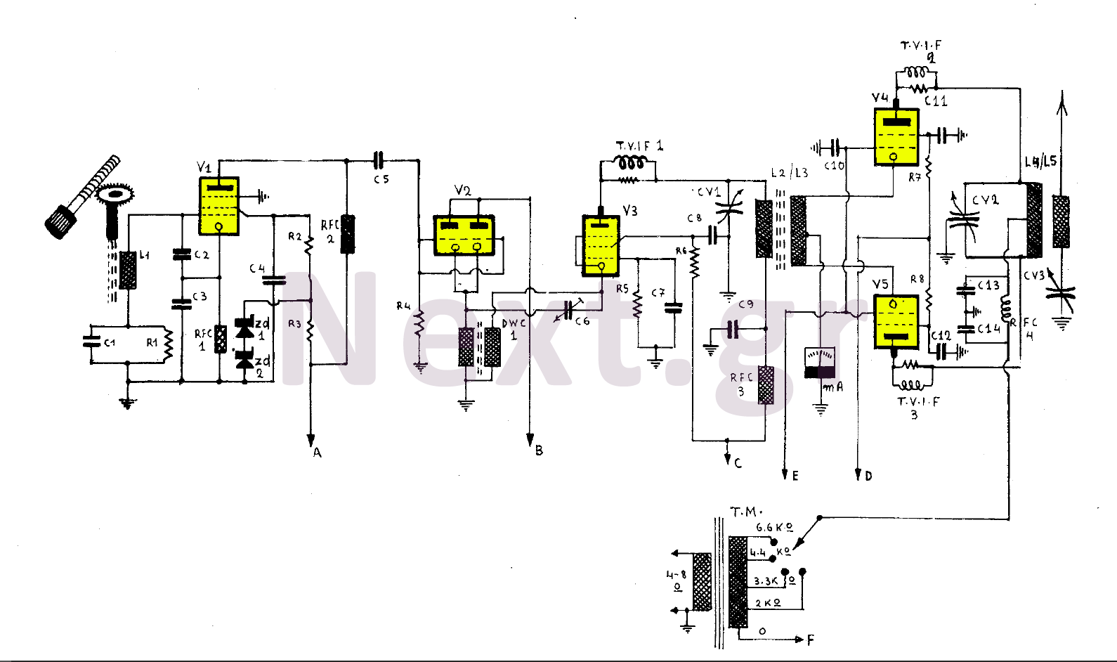
This 255W transmitter operates using coils designed for both medium and short waves. The antenna power is set at 255W and includes four operational states. The first state utilizes an EF80 tube functioning as a Colpitts Clapp oscillator. Frequency...