
Battery Voltage monitor

The battery voltage monitor circuit is designed to provide a visual representation of the voltage level of a 12-volt battery, which is commonly used in various applications such as automotive systems, renewable energy storage, and portable electronic devices. This circuit typically incorporates a voltage divider, which scales down the battery voltage to a lower level suitable for measurement by an analog-to-digital converter (ADC) or a microcontroller.
Key components of the circuit may include resistors, an operational amplifier (op-amp), and a display element such as an LED or an LCD screen. The voltage divider consists of two resistors connected in series, where the output voltage is taken from the junction between the two resistors. This output voltage can then be fed into the ADC of a microcontroller, which converts the analog voltage to a digital value for processing.
The op-amp can be used to amplify the voltage signal if necessary, ensuring that the measurement is accurate and within the operational range of the ADC. Additionally, the circuit may include protection features such as fuses or diodes to prevent overvoltage or reverse polarity conditions that could damage the components.
The display element provides a user-friendly interface, allowing users to easily read the battery voltage level. In more advanced designs, the circuit may also include features such as low battery alerts, data logging capabilities, or connectivity options for remote monitoring.
Overall, the battery voltage monitor circuit plays a crucial role in ensuring the reliable operation of battery-powered systems by providing real-time voltage information and enabling proactive maintenance.Battery Voltage monitor is used to indicate the voltage level of 12 volt battery circuit of battery voltage monitor verified electronics project circuit with description. 🔗 External reference
Related Circuits
This circuit accepts positive, negative, or differential control voltages. When the control voltage is zero, the output frequency is also zero. The described circuit functions as a versatile control voltage interface, capable of processing a range of input signals, including...
A voltage window switch is in practice the basic lower window limit of this circuit is roughly 3V and the upper limit is 9V. The window range can be extended by fitting a suitable range Part List R1-2=10Kohm D1=9V1/ 0.5W Zener...
A pair of cross-coupled SCRs can be utilized to create a first-response monitor circuit, as illustrated in the schematic diagram below. The first-response circuit is... In the context of electronic monitoring systems, a first-response monitor circuit employing cross-coupled Silicon Controlled...
This battery allows the indicator to the car battery voltage monitor. The indicator has four LEDs which indicate power. The more LEDs, the higher the voltage. The last LED is a flashing LED. It comes on when the accuspaning...
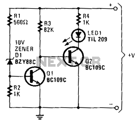
When the battery voltage exceeds approximately 11 V, current flows through resistors R1, D1, and R2. The voltage generated due to the current flowing through R2 is sufficient to turn on transistor Q1, effectively bringing its collector voltage near...
A car battery charger schematic and description. This 12V automatic car battery charger circuit can also be used for charging other automobile batteries. The described circuit is a 12V automatic car battery charger designed for efficient charging of various automobile...