
car battery charger

The described circuit is a 12V automatic car battery charger designed for efficient charging of various automobile batteries. The circuit typically consists of a transformer, rectifier, voltage regulator, and a control circuit.
The transformer steps down the AC voltage from the mains supply to a suitable level for charging the battery. The output of the transformer is then fed into a rectifier, which converts the AC voltage into DC voltage. This is essential for charging batteries, as they require direct current for charging.
Following the rectification, a voltage regulator is employed to maintain a constant output voltage, ensuring that the battery receives a stable and safe charging voltage. This is particularly important to prevent overcharging, which can damage the battery and reduce its lifespan.
An automatic control circuit is often included to monitor the battery voltage and current. This control circuit can disconnect the charger when the battery reaches full charge, thus preventing overcharging. Additionally, some designs may incorporate LED indicators to provide visual feedback on the charging status.
Overall, this 12V automatic car battery charger circuit is versatile and can be adapted for various types of batteries, making it a valuable tool for automotive maintenance and care. Proper attention to component ratings and circuit design will ensure reliable performance and longevity of both the charger and the batteries being charged.A car battery charger schematic & description . This 12v automatic car battery charger circuit can be also use for charging other automobiles batteries. .. 🔗 External reference
Related Circuits
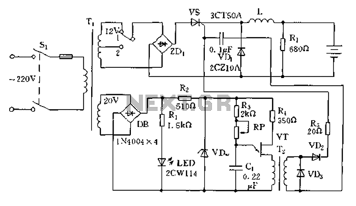
The circuit operates on the principle of a transformer, bridge rectifier, and conditioning for battery charging. The charging current can be adjusted to approximately 12V at 100A. For battery charging, a charging rate of 10 hours requires a charging...
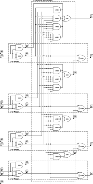
A 4-bit Carry Look Ahead Adder has 3 gate delays for all carry bits and 4 gate delays for all sum bits, whereas ripple adders have 7 and 8 gate delays, respectively. The 4-bit Carry Look Ahead Adder (CLA)...
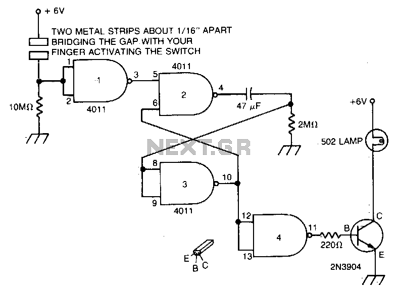
Touch the plate, and the light will turn on and remain on due to the 47 µF capacitor and the 2MΩ resistor for a duration determined by the timing resistor. The circuit described involves a touch-sensitive plate that activates a...
The Park Aid system utilizes three LEDs to indicate the distance of a bumper barrier through infrared operation, designed for indoor use. The circuit diagram includes the following components: R1 (10K 1/4W resistor), R2, R5, R6, R9 (1K 1/4W...
The diagram illustrates the principle circuit of a radio control car receiver. Important notes include the selection of transistor Q1, which is specified as either 1815 or 9018, along with the bias resistor R1, which has values of 240K...
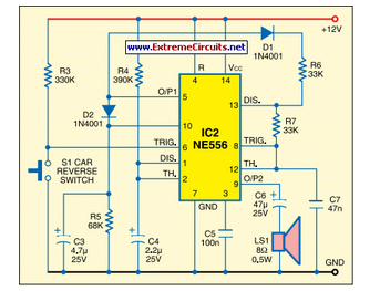
This circuit activates the car horn when the vehicle is in reverse gear. It utilizes a dual timer NE556 to generate the necessary signals. The described circuit employs a dual timer IC, specifically the NE556, which is a versatile component...