
Battery voltage monitor circuit by LM339

The low voltage tester circuit is designed to provide a reliable method for monitoring the voltage levels of batteries and other power sources. The circuit typically includes a voltage divider, which scales down the voltage to a level that can be safely processed by a microcontroller or comparator.
An LED display is incorporated to visually indicate the voltage status. It may consist of multiple LEDs, each representing a specific voltage range, allowing for quick assessment of the battery's condition. When the voltage falls below a predetermined threshold, an alarm sound is triggered, alerting the user to potential issues with the power source.
Powering the circuit can be achieved through the battery being tested or an external power supply. The use of low-power components ensures that the circuit does not significantly drain the battery being monitored.
Additional features may include a reset button to silence the alarm and reset the display, as well as calibration options to adjust the voltage thresholds according to different battery types. This circuit is suitable for a variety of applications, including testing household batteries, automotive batteries, and other low-voltage power supplies.
Overall, this low voltage tester circuit is an essential tool for ensuring the reliability and performance of various voltage sources in electronic applications.This simple low voltage tester circuit can be used to monitor battery and other voltage sources of current for problems, by LED display and alarm sound. Which.. 🔗 External reference
Related Circuits
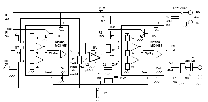
The objective of this project was to create a custom device utilizing local manufacturing resources. At that time, there was a pressing need for a Dub Siren. A circuit diagram was located, and with the assistance of an electronics...
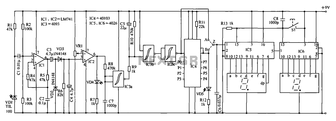
The digital counter circuit described utilizes an infrared signal to detect moving targets, making it suitable for counting small devices on a production line as they move along a conveyor belt. This circuit can also be employed for various...
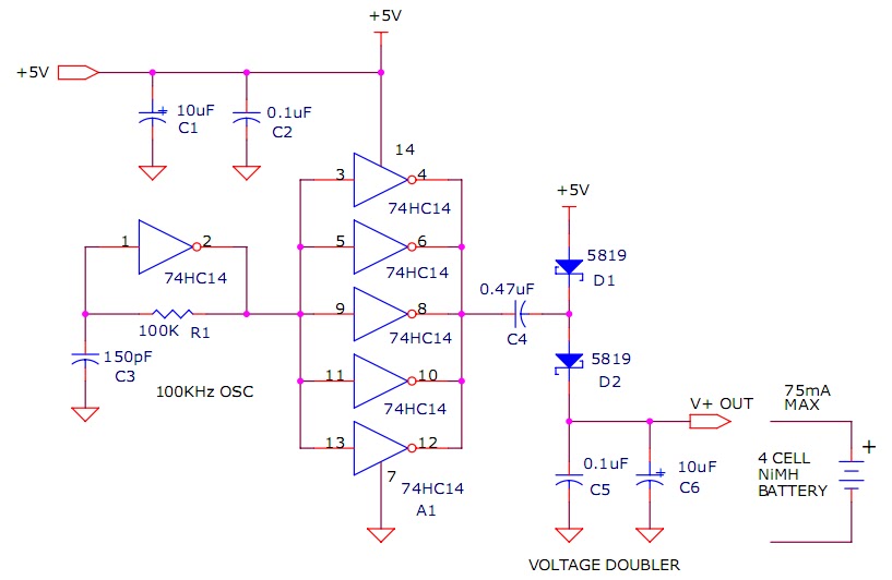
The circuit described will trickle charge a four-cell pack of AA or AAA NiMH batteries. It draws current from the +5V available from a USB connection and supplies approximately 70mA of current to the battery. This current level is...

The schematic for this project is not overly complex; however, it is crucial to understand the circuit board and its operation due to the high voltages generated. Below is a rough draft schematic of the camera used for this...
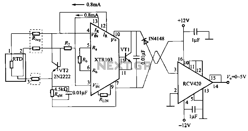
When the RTD temperature sensor is positioned far from the amplifier, the resistance of the sensor leads and their susceptibility to interference and other issues cannot be overlooked. The circuit shown in the figure addresses this problem. It utilizes...
This circuit provides a visual 9-second delay using 10 LEDs before closing a 12-volt relay. When the reset switch is closed, the 4017 decade counter is reset to the 0 count, illuminating the LED driven from pin 3. The...