
RTD remote temperature sensing current voltage conversion circuit

The described circuit effectively mitigates the challenges associated with RTD temperature sensors located at a distance from the amplifier. The XTR103 voltage-to-current converter plays a pivotal role in this configuration. By converting the RTD's resistance changes into a proportional current signal, the XTR103 ensures that the temperature readings remain accurate despite potential lead resistance and electromagnetic interference.
The circuit's design includes two 0.8mA current sources, which are critical for driving the RTD sensor. The use of VT2 allows for stable operation by isolating the RTD from the effects of lead resistance and noise, thereby maintaining the integrity of the temperature measurement. The resistors Rh and R are crucial for setting the maximum allowable current output, which prevents saturation and ensures the system operates within its designed parameters.
Moreover, Rini serves as a fine-tuning element for linearization, enabling adjustments to be made for optimal performance. This is particularly important in applications requiring precise temperature measurements, where even minor deviations can lead to significant errors.
The output stage of the circuit, which includes the external crystal tube VT1, converts the current signal into a 4-20mA format, a standard in industrial applications for transmitting analog signals over long distances. The subsequent conversion by the RCV420 from current to voltage results in a 0-5V output, facilitating easy interfacing with various monitoring and control systems.
In summary, the circuit effectively enhances the reliability and accuracy of RTD temperature measurements in environments where sensor lead resistance and interference are concerns, making it a valuable solution in industrial and laboratory applications.When the RTD temperature sensor further away from the amplifier, sensor lead resistance and the lead is vulnerable to interference and other issues will not be ignored. Circuit shown in Figure can solve this problem. The circuit uses a voltage-current converter -4-20mA XTR103. XTR103 dedicated to RTD signal processing path, the internal integration RrlD linear circuit, widening the supply voltage range of + 9 ~ + 40V. XTR103 two output 0.8mA current source, a current source after driving through VT2 applied RTD, avoid links from decay, and inhibited the line interference.
Rh and XTR101 role in R. Exactly the same role: defining output maximum current. Rini linearized adjusting the resistance, the resistance to change that is to change the linearity. Output signal via an external crystal tube VT1 obtained after 4 ~ 20mA current. RCV420 dedicated to 4-20mA current-voltage converter (in this section, "three" will be introduced), after converting the output voltage of 0 ~ 5V
Related Circuits
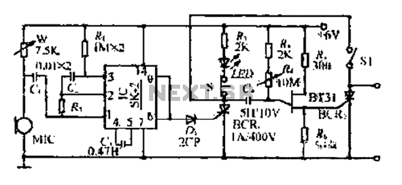
The circuit includes a microphone (MIC) housed in a cylindrical body that captures sound when an object makes contact. The audio signal is coupled to an integrated circuit (IC) for amplification. The output from the IC, at pins 6...
Battery Indicator Circuit for the Caravan. This i-TRIXX circuit can prevent a lot of trouble for those who go on holiday in a caravan. It would be a significant damper on your holiday spirit when you are unprepared. The Battery...
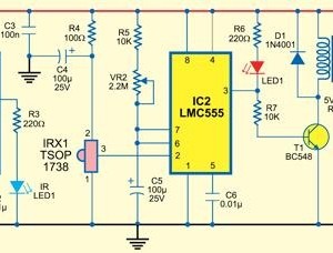
This type of infrared proximity circuit is commonly utilized as an electric switch where physical contact is undesirable for hygiene reasons. For instance, infrared proximity sensors are frequently found in public drinking fountains and washrooms. The straightforward circuit described...

This circuit exhibits an exceptionally fast high-frequency response, as demonstrated by applying a 100 kHz square wave to the input. All graphs were produced using Tina Pro. The circuit's design is optimized for high-frequency applications, showcasing rapid response times that...
Bridged resistive sensing elements are commonly used in resistive type sensors and transducers. This type of sensor requires a biasing voltage to operate. The LM10 provides low... Bridged resistive sensing elements are integral components in various resistive sensors and transducers,...
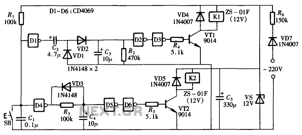
A one-button control switch is designed to control two relays, each of which can switch the load power on and off as needed. The circuit primarily consists of a hex inverter CD4049 and two self-locking DC relays. The circuit utilizes...