
BBE monolithic integrated circuit M2150A

The 4V flat monitor high voltage power supply circuit is designed to provide a stable and efficient voltage source for flat panel displays. This circuit typically includes components such as a transformer, rectifier, and voltage regulator to convert high voltage input into a usable 4V output. The design ensures that the monitor operates within its specified voltage range, preventing damage from over-voltage conditions.
The DC-DC step-down circuit, which can accept an input voltage range of 7V to 40V and output a regulated 5V, employs a buck converter topology. This circuit utilizes an inductor, a switch (typically a MOSFET), and a diode to efficiently convert the higher input voltage to a lower output voltage while minimizing power loss. The switching frequency and duty cycle are critical parameters that must be optimized to achieve high efficiency and low ripple in the output voltage.
The light control switch circuit diagram emphasizes safety by integrating features such as overload protection and short-circuit prevention. This circuit may include a relay or a solid-state switch that controls the light load based on input signals, ensuring that the lighting system operates safely under varying conditions.
The 555 timer circuit is a versatile component often used in control applications, including photoelectric systems. In this configuration, the 555 timer can be set up in either monostable or astable mode to create timing pulses or oscillations that control other components in the system. This allows for precise control of devices based on light detection, enhancing the overall functionality of the circuit.
These circuits are integral to modern electronic applications, providing reliable power management and control solutions across various devices and systems.4V flat monitor high voltage power supply circuit diagram innocentA wide range of 7 ~ 40V turn 5VDC-DC step-down circuit diagramLight control switch circuit diagram of a safety circuit555 constitute a control circuit diagram of a photoelectric
Related Circuits
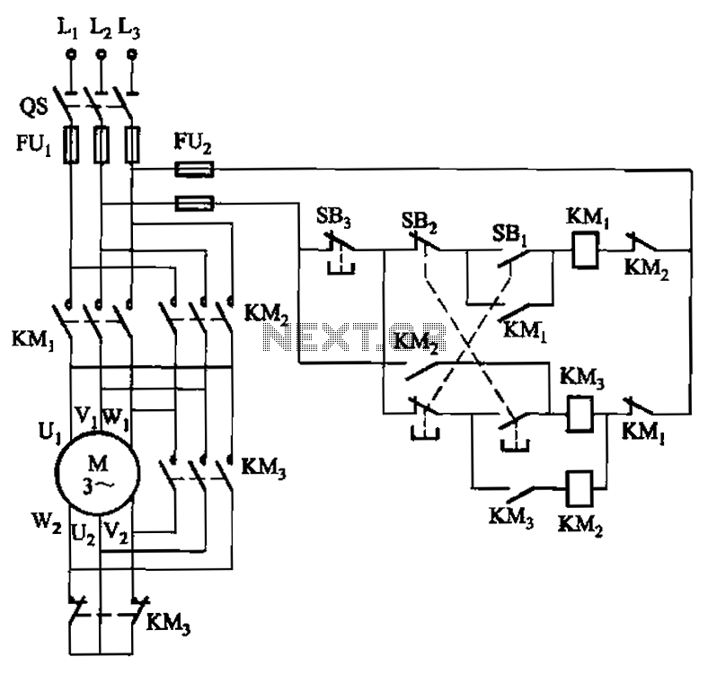
A hoist rated at 22kW and below is equipped with a power-saving Y-conversion circuit, as depicted in the figure. This circuit enhances the standard hoist design by incorporating a CJ20-10A exchange contactor. The implementation of the Y-conversion circuit during...
Circuit diagram schematics of electronic keys, electronic locks, digital electronic locks, transistor code locks, and combination electronic locks. The circuit schematics for electronic locking mechanisms encompass a variety of designs tailored to enhance security and convenience in access control systems....
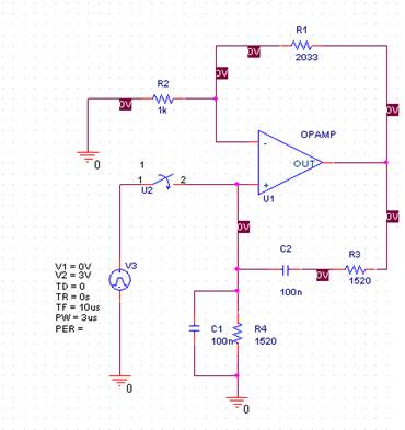
In this laboratory experiment, the objective is to design the frequency-determining network for a 1 kHz sinusoidal oscillator. The specified values are as follows: Capacitance = 100 nF and Resistance = 1520 ohms. The output voltage waveform of the...
This power supply utilizes a single 7812 IC voltage regulator along with multiple external pass transistors, enabling it to deliver output load currents of up to 30 amps. The circuit design incorporates a 7812 linear voltage regulator, which is...
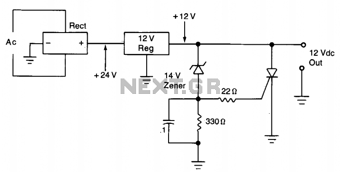
The silicon controlled rectifier (SCR) is designed to handle at least the current provided by the power supply. It is connected in parallel across the 12 V DC output lines but remains inactive until a voltage is applied to...
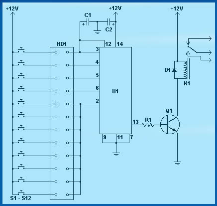
If a page name is not selected by pressing the button, the previously selected page name continues to be used. The value is stored in EEPROM and may be changed at any time. When the unit is first powered...