
Wien bridge oscillator circuit

The output voltage waveform of the oscillator varies with changes in the value of R1. When R1 is set to 2033 ohms, the loop gain approaches 1, resulting in sustained oscillation. If R1 is adjusted to 2.1 k ohms, the loop gain exceeds 1, leading to overdamping of the oscillation. Conversely, setting R1 to 1.9 k ohms causes the loop gain to drop below 1, resulting in underdamping of the oscillation.
To design a 1 kHz sinusoidal oscillator, a frequency-determining network can be constructed using a combination of resistors and capacitors. The fundamental frequency (f) of the oscillator can be calculated using the formula:
\[ f = \frac{1}{2\pi R C} \]
Where:
- \( f \) is the frequency in Hertz (Hz),
- \( R \) is the resistance in ohms (Ω),
- \( C \) is the capacitance in farads (F).
Given the parameters of 100 nF for capacitance and the resistance value of 1520 ohms, the frequency can be verified as follows:
\[ f = \frac{1}{2\pi (1520)(100 \times 10^{-9})} \approx 1.05 \text{ kHz} \]
This indicates that adjustments to the resistance will be necessary to achieve the desired frequency of 1 kHz.
The oscillator's performance is sensitive to the feedback network, which is where R1 comes into play. By adjusting R1, the loop gain of the oscillator can be manipulated, affecting the stability and nature of the oscillation.
- When R1 is set to 2033 ohms, the loop gain is approximately 1, which is critical for maintaining stable oscillation. This is the ideal condition for the oscillator to function effectively without decay or excessive growth of the output signal.
- Increasing R1 to 2.1 k ohms results in a loop gain greater than 1, which introduces overdamping. In this scenario, the oscillator may struggle to produce a consistent waveform, leading to a slower response and potentially a damped oscillation that eventually settles at a steady state.
- Conversely, reducing R1 to 1.9 k ohms causes the loop gain to fall below 1, resulting in underdamped oscillation. This condition may cause the output waveform to exhibit ringing or oscillations that decay slowly, which may be undesirable for certain applications requiring a clean sinusoidal output.
In practical applications, careful selection of R1 in conjunction with the fixed resistance and capacitance values will allow the designer to achieve the desired oscillation characteristics for specific circuit requirements.In this laboratory experiment, we need to design the frequency determining network for a 1k Hz sinusoidal oscillator. Therefore, we should set: Capacitance = 100nF Resistance = 1520 ohm
Output voltage waveform of oscillator with varying the value of R1:
Set R1 = 2033 ohm (The loop gain is about to 1, sustained oscillation is resulted.)
Ser R1=2.1k ohm (The loop gain is greater than 1, overdamping oscillation is resulted.)
Set R1= 1.9k ohm (The loop gain is smaller than 1, underdamping oscillation is resulted.)
🔗 External referenceRelated Circuits
The circuit is a bell timer. This project utilizes the AT89S52 microcontroller and an I2C EEPROM for storing alarm timings. Additionally, the 7-segment display has been replaced with an LCD display. The DS1307 is employed for real-time clock functionality....
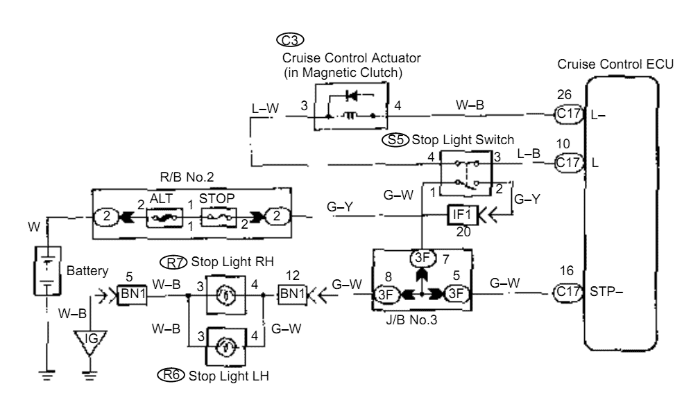
When the brake pedal is depressed, battery positive voltage normally applies through the STOP fuse and stop light switch to terminal STP of the ECU, and the ECU turns the cruise control off. A failsafe function is provided so...

The demonstration circuit operates in the HM2007's manual mode. This mode uses a simple keypad and digital display to communicate with and program the HM2007 chip. When the circuit is turned on, the HM2007 checks the static RAM. If...
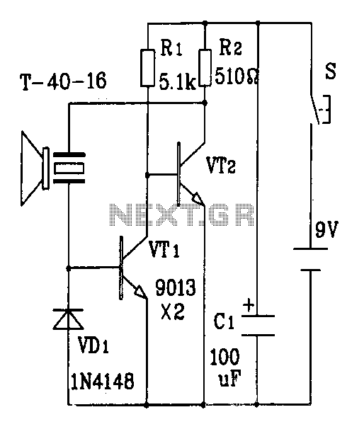
The discrete components ultrasonic transmitter circuit T/R-40-16 can emit a series of ultrasonic signals at a frequency of 40 kHz. This circuit operates at a voltage of 9V and has a current consumption of 25mA, with a control distance...
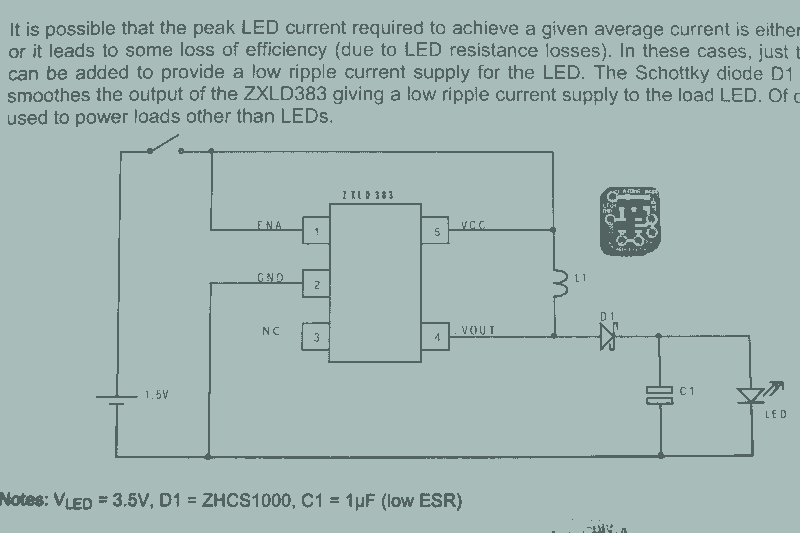
It may seem that due to the numerous flashlight projects undertaken, there is a significant collection of lights. The inductor can be altered to set the current level, but the total current fluctuates with the battery supply, decreasing as...
The delay-saving lamp circuit functions as a sound and light control delay energy-saving lighting system. It can directly replace a standard light switch without modifying the existing lighting circuits. In bright or daytime conditions, the sound control feature ensures...