
BC547 Single Transistor Radio

The circuit design for a simple radio receiver typically incorporates a single transistor as the active amplification element, along with several passive components such as diodes, capacitors, inductors, and resistors. The primary function of the transistor in this configuration is to amplify the weak radio frequency (RF) signals captured by the antenna.
The circuit can be divided into several key sections: the antenna, the tuning circuit, the detector, and the audio output stage. The antenna collects RF signals from the air, which are then fed into a tuning circuit composed of an inductor and a variable capacitor. This combination allows the user to select the desired frequency by adjusting the capacitance, effectively tuning the circuit to resonate at the frequency of the incoming signal.
Once the signal is tuned, it passes through a diode, which acts as a detector. The diode rectifies the RF signal, converting it into a varying direct current (DC) signal that corresponds to the audio information encoded in the RF wave. Following the detection stage, the audio signal is then filtered using capacitors to remove any high-frequency components, ensuring that only the audio frequencies are passed on.
The amplified audio signal is then sent to the output stage, which may include additional passive components such as resistors to set the gain and capacitors for further filtering. The output can be connected to a speaker or headphones to produce audible sound.
This simple radio circuit exemplifies the fundamental principles of radio communication and can serve as an educational tool for understanding basic electronics, radio frequency principles, and signal processing techniques. Proper component selection and layout are crucial for optimizing performance and ensuring reliable operation of the circuit.the circuit diagram of a simple radio that uses one transistor and few other passive components.. Component: Diode, Capacitor, Inductor, Resistor, .. 🔗 External reference
Related Circuits
The following two-transistor circuit is a preamplifier for magnetic phono cartridges, characterized by its frequency response defined by the RIAA standard for phono recording. This preamp circuit has a gain of approximately 40 dB (midband) at 1 kHz. The...
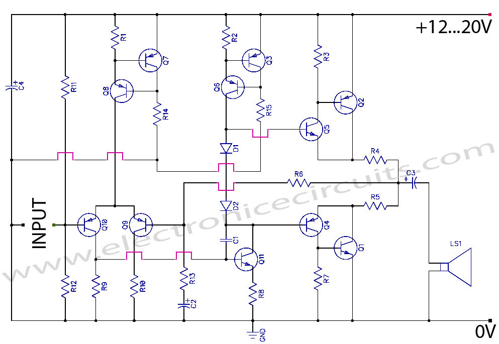
Discrete Class AB Transistor Audio Power Amplifier Circuit Diagram. This is a Class AB transistor power amplifier. It is a simple amplifier. The discrete Class AB transistor audio power amplifier is designed to provide efficient amplification of audio signals while...
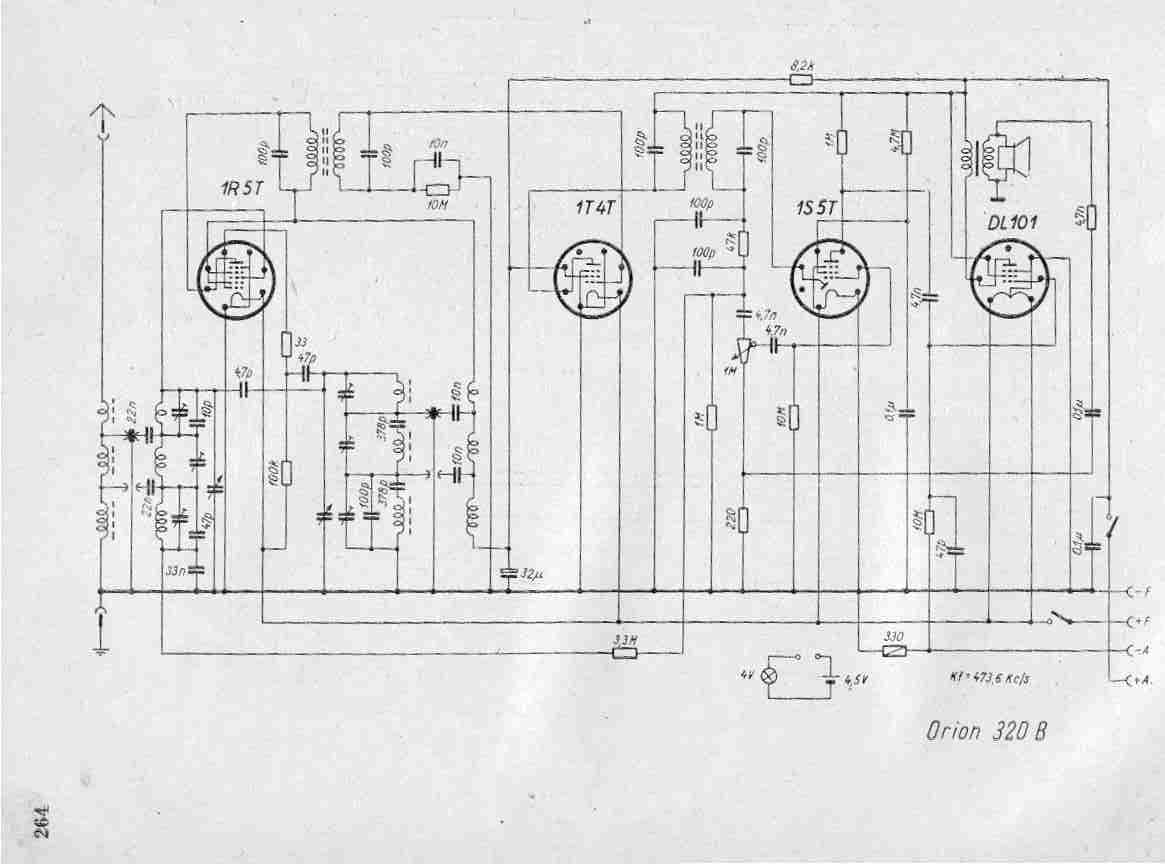
Create a repository of circuits and service data for vintage valve and transistor radios. While many resources are available online, they often come at a cost. The intention is to share circuits and manuals with others rather than profit...
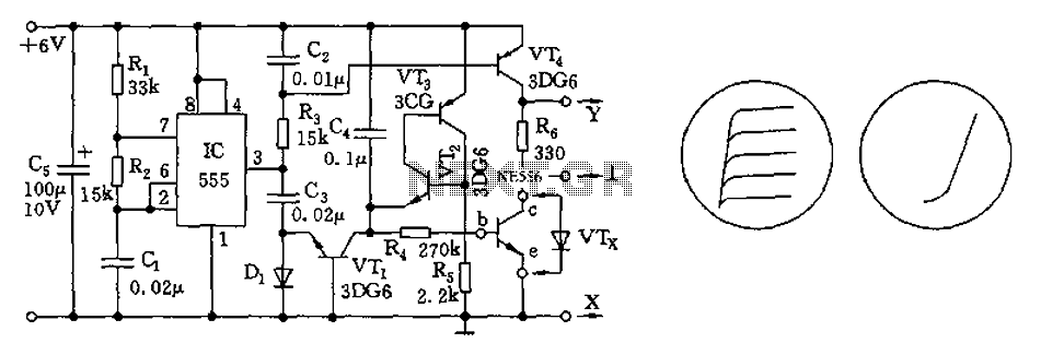
The transistor characteristic curve tracer circuit depicted in Figure 555 illustrates the characteristics of a transistor. It utilizes two voltages: a step wave applied to the base (b) to generate different base currents (Ib), and a sawtooth waveform at...
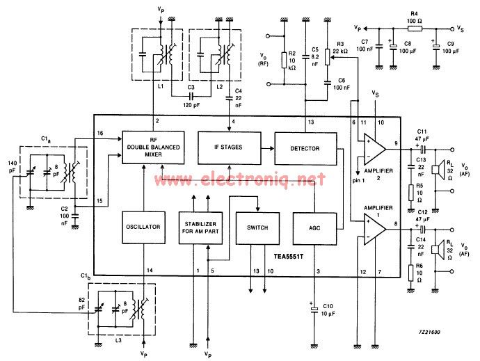
The TEA5551T monolithic integrated radio circuit can be utilized to design an AM radio receiver circuit intended for portable use with headphones. This circuit incorporates all necessary components for a complete AM radio receiver, including a fully integrated AM...
This circuit is designed for low power operation and can be tuned to function within the frequency range of 87-108 MHz, achieving a transmission distance of 20 to 30 meters. The circuit utilizes a pair of BC548 transistors, which,...