
Beam-break Detector For Camera Shutter or Flash Control

This circuit is designed to provide a reliable and efficient method for detecting interruptions in an infrared beam, making it suitable for various applications such as security systems, automated doors, and object detection in robotics. The use of the Jaycar ZD-1942 IR receiver IC ensures that the circuit remains functional in environments with varying ambient light conditions, enhancing its versatility.
The monostable configuration of the LM-7555 timer allows for a predictable output duration, which is crucial for applications requiring a specific response time upon beam interruption. The output duration can be adjusted by changing the timing components associated with IC2, thus providing flexibility in response characteristics.
The low-power relay driven by transistor Q1 is capable of controlling larger loads, making this circuit suitable for activating alarms, lights, or other devices upon detection of an object. The choice of a 5V relay ensures compatibility with the power supply while maintaining energy efficiency.
The transmitter's astable mode configuration allows it to emit a continuous modulated IR signal, which is essential for the receiver to detect interruptions effectively. The 38kHz frequency is a standard choice for IR communications, as it minimizes interference from ambient light sources and other electronic devices.
In summary, this circuit offers a robust solution for infrared beam break detection, with a focus on reliability, flexibility, and ease of integration into various systems. The careful selection of components and configuration allows for effective operation in a range of environments and applications.This circuit is presented as an alternative to the IR beam break detector featured in the June 2009 issue (Silicon Chip). In order to make it relatively insensitive to ambient light, it uses a standard IR receiver IC such as the Jaycar ZD-1942.
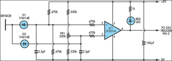
This has a high output ( 5V) as long as a modulated beam is detected. The IR detector (IC3) controls an LM 7555 CMOS timer (IC2) which operates in mono stable mode. When the beam is broken, IC2 is triggered and its pin 3 output goes high for about half a second. This extinguishes LED1 and turns on transistor Q1 to drive a 5V low-power relay. The circuit is powered from six AA cells and a 78L05 5V regulator (necessary for the receiver IC). The IR transmitter is also built around an LM7555 (IC1), this time operating in astable mode at low duty cycle. Its frequency is set to 38kHz with trimpot VR1. The IR diode was salvaged from a defunct remote control but these are readily available new. The transmitter is powered by four AA cells. The system has a range of several metres and while it is insensitive to the transmitter alignment, the detection window can be narrowed by placing the detector near to the object to be detected and/or using some form of baffle to restrict the window.
🔗 External reference
Related Circuits
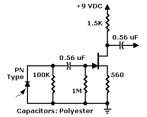
The JFET input configuration is utilized with PN photodiodes, such as the commonly used "bullet cell," which produce extremely low-level signals. Photodiodes provide several advantages over phototransistors, including a faster response to motion and a peak sensitivity within the...
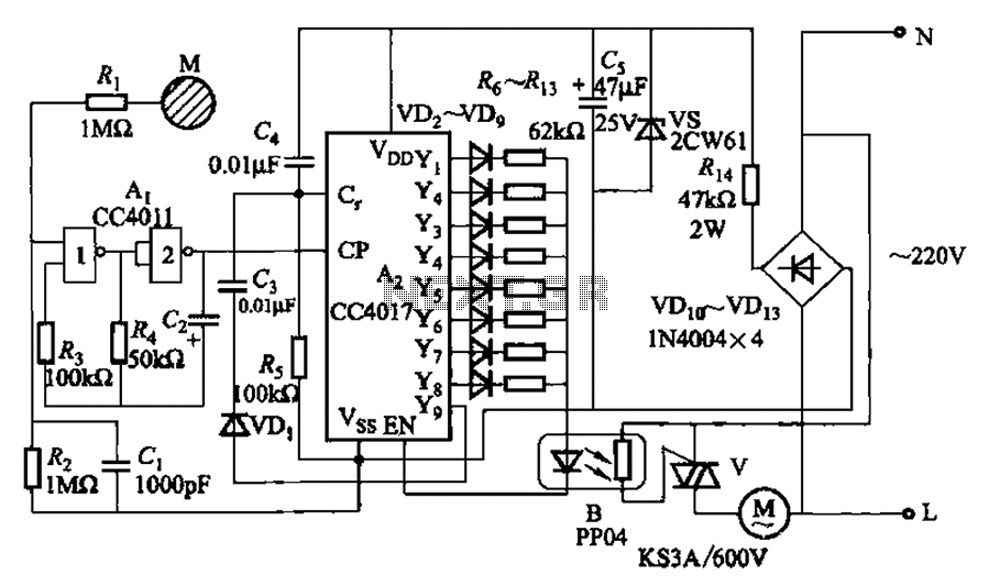
The circuit depicted in Figure 3-7 utilizes a touch sensor chip in conjunction with a conductive sheet. It is designed to achieve eight different speed settings. The CC4011 timing pulse oscillator is comprised of an integrated circuit. The configuration...
It is well known that simple everyday activities, such as walking on a carpet or moving in a chair, can lead to the accumulation of static charge in the body, sometimes reaching thousands of volts. This circuit is designed...
This section describes an experimental low power, low bandwidth data signaling system that was initially made to operate at 55 MHz (television channel 2 in the U.S.). Before operating a radio transmitter, find out what kind of transmitter operation,...
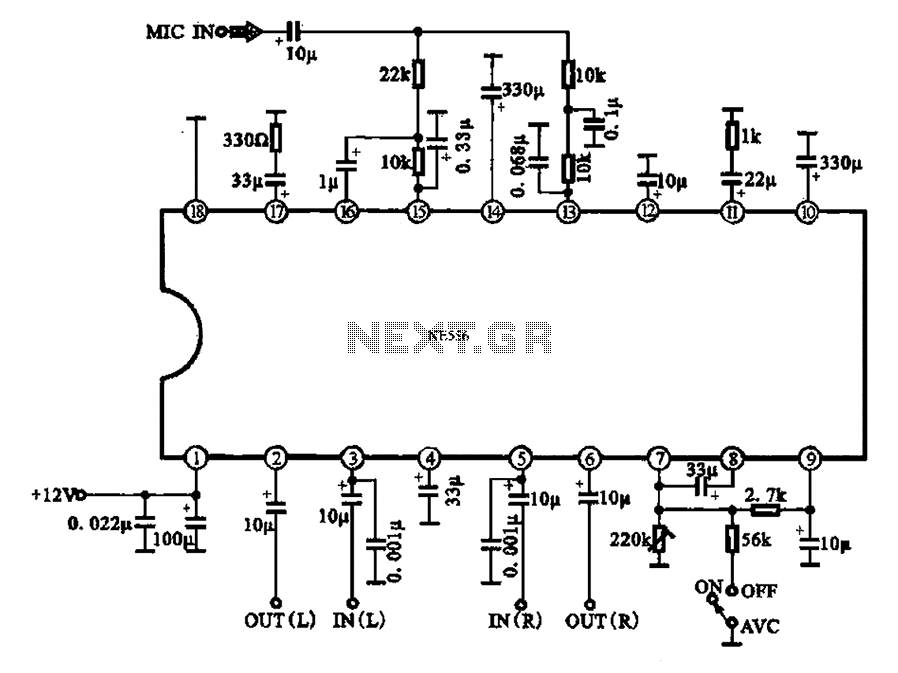
Automatic volume adjustment with ambient noise control circuit. In car stereos and similar devices, the ambient noise level varies during high-speed and low-speed driving or while stationary, leading to different volume requirements. A fixed volume adjustment method may negatively...

The NAND gates utilize a CMOS 4011 chip, which is a low-power component ideal for battery-operated circuits. This chip is powered by a 5V voltage supplied from an LM7805L regulator. The purpose of this regulation is to maintain a...