Body Charge Detector
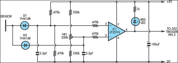
It is well known that simple everyday activities, such as walking on a carpet or moving in a chair, can lead to the accumulation of static charge in the body, sometimes reaching thousands of volts. This circuit is designed to detect not only such charges but also electromagnetic field (EMF)-induced voltages in the body, which are typically much smaller. Consequently, regardless of whether an individual is "charged up" on a given day, it is highly likely that the circuit will be triggered. Notably, the sensor does not need to be metallic; as long as it is isolated from ground, any conductor, including a potted plant, can serve as a sensor. The circuit employs a comparator based on an LF351 FET-input operational amplifier (IC1), which offers a high impedance input critical for detecting static charges. It is essential for the 0V side of the circuit to be connected to earth, such as through a metal stake driven into the ground, to ensure optimal performance. The sensor connections are routed through diodes D1 and D2, allowing both negative and positive charges to elevate the voltage at the inverting input of IC1 above that of the non-inverting input, causing a change in the output. A trimpot (VR1) and two 470 kΩ resistors across the supply are utilized to set the inverting and non-inverting inputs (pins 2 and 3) at approximately half the supply voltage (around +2.5V), while the input resistors safeguard IC1 from potential static damage. The circuit's sensitivity can be adjusted using VR1; higher static charges will cause the red LED to flash brightly, while smaller and rapid discharges may only cause a faint illumination. To enhance the clarity of triggering, the output at pin 6 can be directly connected to the trigger input (pin 2) of a standard 555 monostable timer IC, providing a more definitive indication of activation. This circuit could serve as a valuable indicator of static charge prior to handling sensitive electronic components.
The circuit's design is focused on ensuring high sensitivity and reliability in detecting static electricity and EMF-induced voltages. The LF351 operational amplifier is chosen for its high input impedance, which prevents loading effects that could otherwise diminish the detection capability. The grounding aspect is critical; without a proper earth reference, the circuit's performance will be compromised, leading to inaccurate readings. The use of diodes D1 and D2 is a strategic choice to allow for bidirectional detection of charge, ensuring that both positive and negative static charges are registered effectively.
The adjustable sensitivity feature provided by VR1 allows users to calibrate the circuit based on their specific environment or application. This versatility is particularly beneficial in settings where static charge can pose risks to sensitive electronic components, such as in manufacturing or repair environments. The integration of a 555 timer IC enhances the output signal, allowing for a more pronounced response to static events, which is particularly useful in alerting users to potentially harmful static levels.
Overall, this circuit represents a practical solution for monitoring static charge accumulation, with a design that accommodates various sensor materials and offers adjustable sensitivity, making it an effective tool for preventing damage to sensitive electronic devices.It is well known that through such simple everyday activities as walking on a carpet or moving in a chair, the body accumulates a static charge - sometimes many thousands of volts. Due to its extreme sensitivity, this circuit will detect not only such charges but also EMF-induced voltages in the body, which are generally far smaller.
This means th at, whether you happen to be "charged up" on any particular day or not, your body will almost certainly trigger this circuit. An interesting twist is that the sensor does not need to be made of metal. Provided it is isolated from ground, the sensor can be any conductor, including a plant in a pot. The circuit is a comparator based on an LF351 FET-input op amp (IC1). The has the benefit of a high impedance input which is crucial for detecting a static charge. The other aspect which is crucial is that the 0V side of the circuit must be connected to earth (eg, a metal stake driven into the ground).
Without the grounded connection, the circuit will yield poor results. Notice that the sensor connections are taken through diodes D1 and D2. This means that both negative and positive charges will cause the voltage at IC1`s inverting input to exceed that of the non-inverting input (the voltage at the inverting input rises or that at the non-inverting input falls). Trimpot VR1 and the two 470kO resistors across the supply are used to set the inverting and non-inverting inputs (pins 2 and 3) at around half-supply (ie, +2.
5V), while the two 470kO input resistors protect IC1 against damage from static. The sensitivity of the circuit is adjusted by VR1. While higher static charges will brightly flash the red LED, small and very rapid discharges through the sensor may barely illuminate it. The way around this is to feed the output at pin 6 directly to the trigger input (pin 2) of a standard 555 monostable timer IC.
This would then offer a clearer indication of triggering. This circuit could prove particularly useful as an indicator of static charge before handling sensitive components. 🔗 External reference
