
bedside lamp timer schematics

The circuit comprises a dual transistor configuration (Q1 and Q2) that acts as a switch, effectively controlling the power to the load (lamp) and the ICs. The relay, activated by P1, serves as the primary mechanism for switching the circuit on and off. In the initial state, when the circuit is powered, the relay closes, allowing current to flow to the lamp and the integrated circuits. IC2, upon receiving a reset signal at pin 12, begins its oscillation cycle, which is crucial for timing functions within the circuit.
The frequency of oscillation is determined by the RC time constant formed by R4 and C4. The choice of these components directly influences the duration before pin 3 transitions high, which subsequently turns off the entire circuit after the designated time period of approximately 30 minutes. The blinking LED serves as a visual indicator of the operational status of the circuit, providing feedback during the countdown to shutdown. The frequency of the blinking is derived from the output of IC2 at pin 9, which controls the timing of the LED's on-off cycle.
IC1 is configured with two gates in parallel to enhance the current capacity available for driving additional loads, such as a piezo sounder, which can be integrated into the circuit for auditory feedback. This versatility allows for modifications to the circuit based on user requirements. The timing characteristics of the circuit can be easily adjusted by selecting different values for R4 and C4, enabling customization of the operational duration and blinking frequency to suit specific applications.Q1 and Q2 form an ALL-ON ALL-OFF circuit that in the off state draws no significant current. P1 starts the circuit, the relay is turned on and the two ICs are powered. The lamp is powered by the relay switch, and IC2 is reset with a positive voltage at pin 12. IC2 starts oscillating at a frequency set by R4 and C4. With the values shown, pin 3 goe s high after around 30 minutes, turning off the circuit via C3. During the c6 minutes preceding turn-off. The LED does a blinking action by connections of IC1 to pins 1, 2 & 15 of IC2. Blinking frequency is provided by IC2 oscillator at pin 9. The two gates of IC1 are wired in parallel to source more current. If required, a piezo sounder can be connected to pins 1 & 14 of IC1. Obviously, timings can be varied changing C4 and/or R4 values. 🔗 External reference
Related Circuits
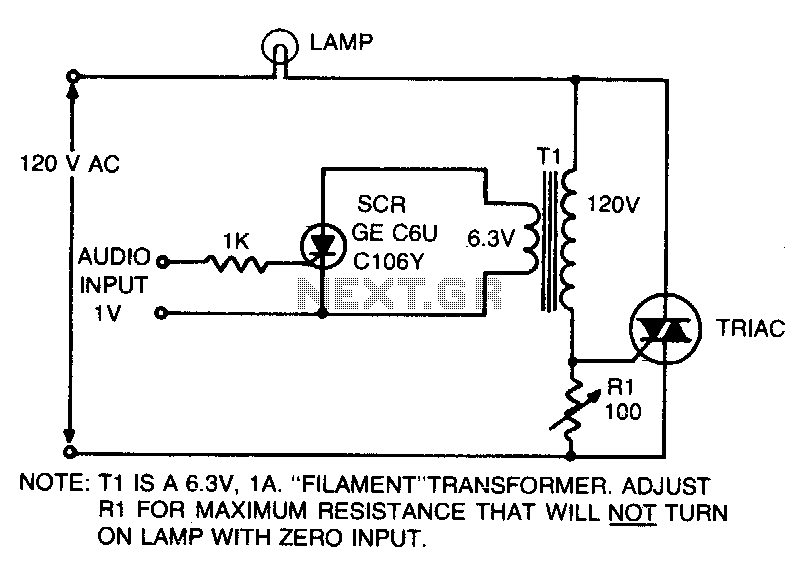
This is an on-off control with an isolated, low voltage input. The switching action occurs rapidly compared to the response time of the lamp and the human eye, resulting in an effect with audio input that resembles a proportional...
The circuit is based on IC1, which is a 555 timer IC in astable mode. It will power a 6 inch 4 Watt fluorescent tube off a 12 volt supply, consuming 300 mA. It may also be powered by...

This timer can be integrated into a power line to provide a controllable delay before a load is activated. The mains voltage is reduced by capacitor C3 and rectified to yield approximately 30 V across capacitor C1. This voltage...

The resulting timer circuit is made from a CD4060, includes an oscillator and a 14 stage binary counter, two CD4040's, which are 12 stage binary counters, a CD4012 Dual Nand gate and a CD4013 Dual D Latch. The CD4060...
This simple alarm timer circuit is constructed using a 4060 integrated circuit, which features a stable oscillator with a relatively wide frequency range. The alarm timer circuit utilizes the CD4060 IC, which combines a low-frequency oscillator and a binary counter....
This circuit is basically the same as the 10 channel LED sequencer with the addition of solid state relays to control the AC lamps. The relay shown in the diagram is a Radio Shack 3 amp unit (part no....