
Neon Desk lamp

The circuit utilizes a 555 timer IC (IC1) configured in astable mode to generate a square wave output that drives a 6-inch, 4 Watt fluorescent tube. The circuit operates from a 12 V DC supply, drawing a current of approximately 300 mA. This design can also accommodate a universal AC/DC adapter, making it versatile for various power sources.
The 555 timer operates as an oscillator, generating a continuous square wave signal that is suitable for driving the fluorescent tube. The current output from the 555 timer is amplified by a transistor (TR1), allowing it to handle the higher current required by the fluorescent tube. The amplified voltage at the collector of TR1 is then fed into a transformer (T1), which steps up the voltage from a mains supply to a 6-0-6 V output. This step-up transformer is crucial for providing the necessary voltage to ignite and sustain the operation of the fluorescent tube.
To ensure reliable operation, it is recommended to use heat sinks for both TR1 and T1 to dissipate heat generated during operation. This will enhance the longevity and stability of the components. Additionally, a variable resistor (VR1) is included in the circuit to allow for adjustment of the output frequency or brightness of the fluorescent tube. It is advised to set VR1 to its maximum resistance of 5 K ohms before applying power to the circuit to prevent excessive current flow during initial power-up.
Overall, this circuit design emphasizes efficiency, utilizing readily available components to achieve good light output while maintaining low power consumption. The simplicity of the design, combined with the use of common stock parts, makes it an attractive solution for powering fluorescent lighting applications.The circuit is based on IC1, which is a 555 timer IC in astable mode. It will power a 6 inch 4 Watt fluorescent tube off a 12 volt supply, consuming 300 mA. It may also be powered by a suitably rated universal AC/DC adapter. Advantages of the design are: good light, low power consumption, and readily available stock parts. IC1`s current output is amplified by TR1, and the voltage at the collector is stepped up by T1, a mains to 6-0-6 V transformer. Heat-sinks are advised for TR1 and T1. Before applying power, VR1 should be advanced to a full 5 K. While power consumptio 🔗 External reference
Related Circuits

The telephone table lamp is designed to automatically illuminate during night ringing or when the phone is off-hook. After hanging up, the lamp will extinguish after a delay of 45 seconds. It is typically used as a general-purpose lamp...

As an alternative to a bipolar transistor, a lamp flasher can be constructed using two power FETs. Similar to other flasher circuits, this circuit alternately switches the... The proposed lamp flasher circuit utilizes two power Field-Effect Transistors (FETs) to control...
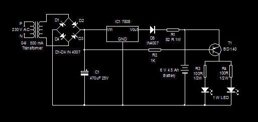
This is a high-efficiency emergency lamp that utilizes high-brightness white LEDs. It automatically activates during power failures and deactivates when power is restored. The emergency lamp circuit is designed to provide reliable illumination during power outages, utilizing high-brightness white LEDs...
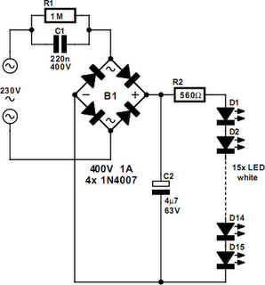
An array of white LEDs can serve as a compact lamp for living spaces. These LED lamps are commercially available and resemble standard halogen lamps, fitting into typical 230-V light fixtures. Upon inspection, it is evident that a capacitor...
This unique and simple multivibrator circuit comprises only five components and operates without vacuum tubes or semiconductors, utilizing two miniature NE2 type neon lamps. It is best suited for interfacing with high-impedance circuits, such as those involving vacuum tubes...
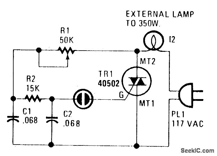
A heatsink allows the TRIAC (TR1) to manage power levels up to 350 watts. The neon lamp (I1) will not activate the gate until it is in conduction, and resistor R1 is used to adjust the lighting level as...