
Bell Timer Circuit using AT89S52

The bell timer circuit is designed to provide a versatile solution for managing timed alerts in various applications such as alarm systems and educational institutions. The core of the system is the AT89S52 microcontroller, which is responsible for processing user inputs, managing the real-time clock, and controlling the output to the relay that activates the bell.
The integration of the I2C EEPROM allows for the storage of up to 25 distinct alarm timings, enhancing the functionality of the timer. This memory component ensures that the settings are retained even when the power is turned off, providing reliability in the system's operation. The use of the DS1307 real-time clock chip enables accurate timekeeping, allowing the user to set precise timings for the alarms.
To facilitate user interaction, a 4x3 keypad is implemented for inputting the desired alarm times and for configuring the real-time clock. This keypad interface is essential for ensuring ease of use, allowing users to navigate through options and set parameters without complexity.
The LCD display replaces the traditional 7-segment display, offering improved readability and the ability to display more information at once, such as the current time and the status of the alarms. This visual feedback is crucial for users to monitor the system effectively.
The ULN2003 is a key component in driving the relay, which ultimately controls the bell. This relay acts as a switch that activates the bell when the specified alarm time is reached. The ULN2003 is a Darlington transistor array that provides the necessary current amplification to drive the relay coil, ensuring reliable operation.
Overall, this bell timer circuit combines modern components and user-friendly interfaces to create a robust solution for timed alert systems, making it suitable for various applications. The schematic diagram associated with this project would illustrate the connections between these components, providing a clear reference for assembly and troubleshooting.The circuit is bell timer. This new project uses AT89S52 microcontroller and I2C EEPROM to store the alarm timings. Also the 7segment display is replaced with LCD display. DS1307 is used for Real time clock. The user can store upto 25 bell timings and they can even set the time delay for bell ringing in seconds. An 4G—3 keypad is used to enter t he real time clock and the bell timings. ULN2003 is used to drive the relay for the bell. this circuit can used by alarm timer, school bell, etc. Here is a schematic drawing: 🔗 External reference
Related Circuits
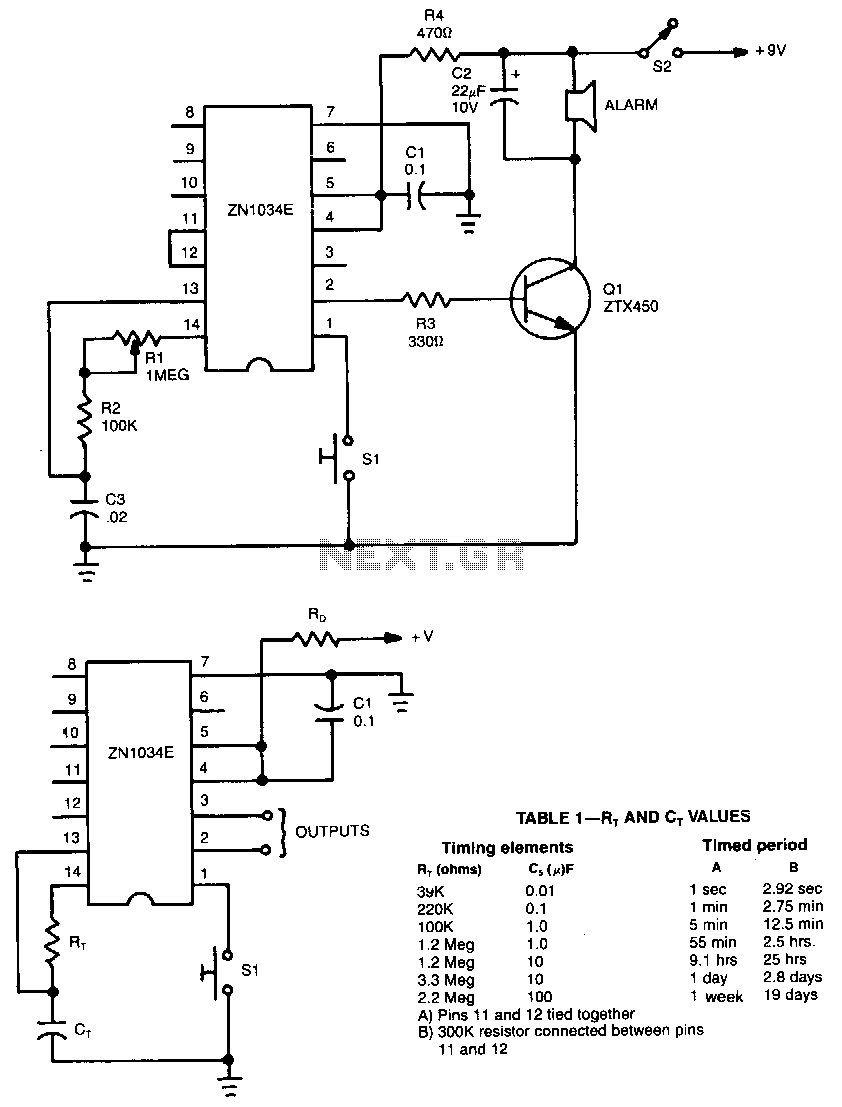
When used as a stand-alone device, the ZN1034E from Ferranti can provide timed intervals ranging from 1 second to 19 days, although the RC time constant is only 220 seconds. The ZN1034E includes an internal voltage regulator, an oscillator,...

This circuit is particularly beneficial for hobbyists using a breadboard to experiment with ideas, as well as those employing a simple homemade DC power supply that consists of a transformer, rectifier, smoothing capacitor, and protective fuse, specifically one lacking...
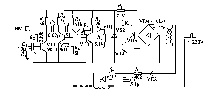
Cook in advance to open the door with a coal stove; before using the fire, it should be strong. This is an automatic door opening device that can automatically open the door before the regular homeowner, eliminating the need...
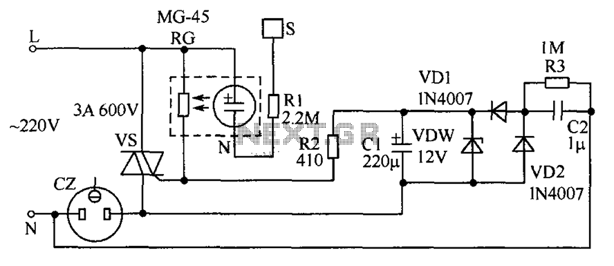
The circuit operates by detecting a finger touch on a metal sheet (S), which activates a neon tube light (N). The combination of the neon tube and a photoresistor (RG) acts as an optocoupler, reducing the resistance of RG....
A sawtooth wave oscillator circuit can be implemented using several methods. Here, one design that employs the 555 integrated circuit is presented, along with its schematic diagram. The sawtooth wave oscillator utilizing the 555 timer IC operates in astable mode,...
When fast charging a nickel-cadmium battery, the temperature control circuit, as illustrated in the accompanying figure, is designed to monitor the battery temperature to regulate the charging current. The circuit consists of Icl to IC3, which forms the temperature...