
Touch the socket circuit diagram

The circuit utilizes a TRIAC (VS) to control the AC load connected to the socket (CZ). The operation begins with the finger touch on the metal sheet (S), which causes the neon tube (N) to illuminate. This illumination decreases the resistance of the photoresistor (RG), allowing current to flow and trigger the TRIAC (VS). The TRIAC serves as a switch, controlling the power to the load based on the trigger current it receives.
The AC voltage from the power supply passes through bulk capacitors (C2) and diodes (VD1 and VD2), which rectify the AC signal into a DC voltage. This DC voltage is then regulated by a zener diode (VDW) to ensure a stable output voltage, which is essential for the reliable operation of the circuit. The filtered output is applied to resistor (R2) that is connected to the gate of TRIAC (VS), ensuring that the TRIAC remains in the conducting state even after the finger is removed from the metal sheet.
The circuit's design allows for a load capacity of up to 500W, making it suitable for various applications. The feature that prevents the socket from becoming live when no load is connected adds a layer of safety, ensuring that the circuit does not waste power or pose a risk when idle. The choice of components, including the MG-45 photoresistor and standard neon tube, reflects a balance between performance and availability, ensuring that the circuit operates effectively while remaining cost-efficient.
Overall, the circuit is efficient and user-friendly, providing a reliable means of controlling an electrical load through a simple touch interface while maintaining safety and energy efficiency. Circuit as shown, with a touch of a finger when the metal sheet S, N neon tube light, since N and photoresistor RG constitute optocouplers make RG resistance becomes smaller, s o the TRIAC VS because sufficient trigger current lead pass, it was electric socket load CZ on working. At the same time, 220V AC voltage through the CZ bulk capacitors C2, the diode VD1 and VD2 rectifier, regulator VDW regulator, filter capacitor C1 obtained by the DC voltage applied to the resistor R2 VS the gate, even if S has left finger touch, VS remains turned on, so that the load connected to the CZ normal power work.
When power is restored after power outage, because VS has not been enough to trigger current, it is not turned on, the load on the CZ is powered off. Only CZ retouches to make the load on the power. When not connected to the load circuit, the socket itself has little power (about 0.5W). Socket load capacity of up to 500W. The circuit also has a feature: when there is no load on the socket, even though the touch of S, the socket is not live.Component selection: Choose a neon tube N ordinary neon tubes, photoresistor RG choose MG-45 models.
VDW select regulator for the 12V zener diode. Resistor selection (1/4) Ws. Other components shown in FIG.
Related Circuits
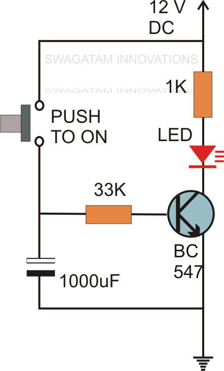
Without the specified delay, the circuit could malfunction or even sustain damage. A capacitor, which is a crucial component of the circuit, is positioned at the other end of the base resistor rather than directly connected to the base...
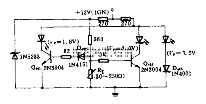
The circuit diagram illustrates how an oil pressure sensor is transformed into a variable resistor, denoted as Rt. Variations in Rt lead to changes in the biasing of each transistor, which in turn controls three LEDs (red, yellow, and...
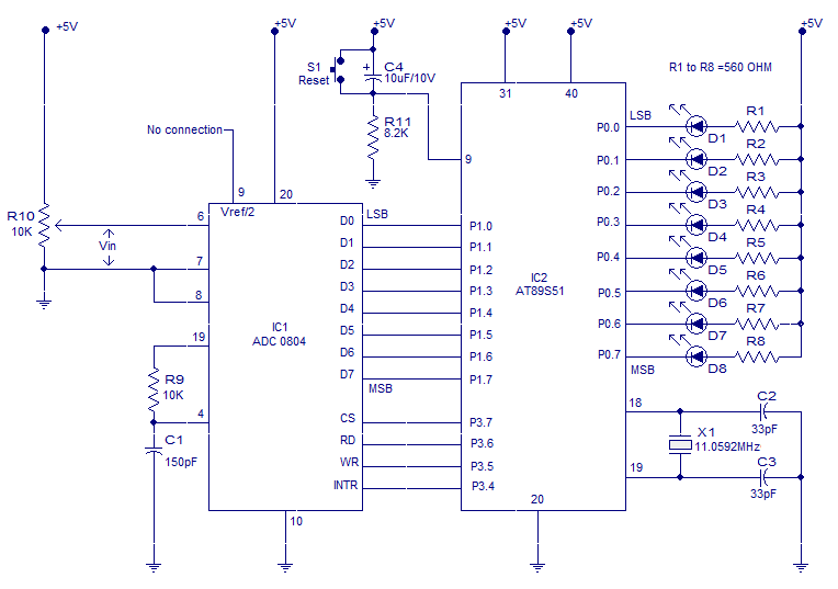
Interfacing ADC to 8051 microcontroller. ADC0804 is interfaced to microcontroller AT89S51. Complete circuit, theory and program in assembly language. The interfacing of an Analog-to-Digital Converter (ADC) with a microcontroller is a critical aspect of embedded systems design, particularly when analog...
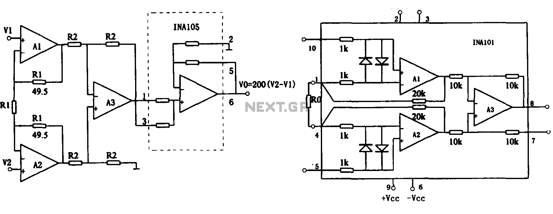
This document describes the extended common mode input voltage range of an instrument amplifier circuit. The circuit consists of three precision instrument amplifiers, A1, A2, and A3, which can be INA101 or INA102 models. The figure illustrates that A1,...
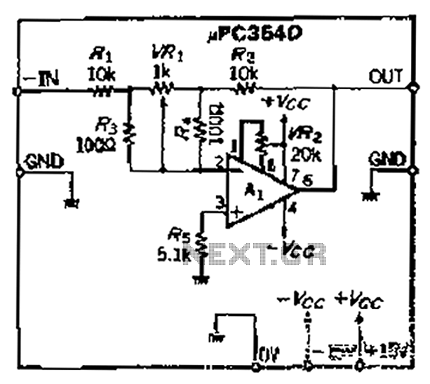
The loop gain of the operational amplifier (OP) is primarily influenced by the ratio of the input resistor to the feedback resistor. Consequently, any resistance error can lead to a corresponding gain error, which necessitates the use of high-precision...
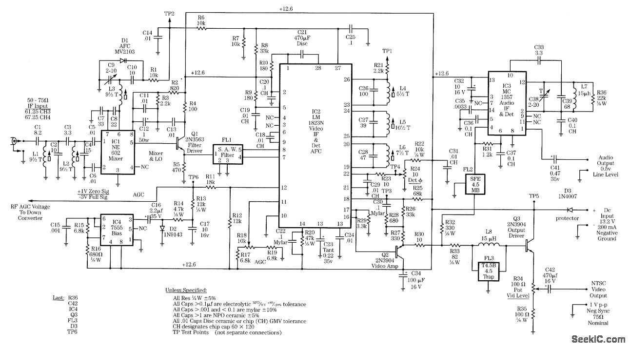
Radio-frequency schematics (also see NE602 datasheet and application note). This page contains electronic circuits related to RF receivers. This index features a broad collection of RF receiver circuits. Radio-frequency (RF) schematics are essential for designing and implementing circuits that operate...