
Bells Ring Generator Electronic

The Bell Ring Generator circuit is designed to produce a dual-tone output that mimics the sound of traditional bells. This type of circuit is commonly used in applications such as doorbells, alarm systems, and notification devices. The primary components typically involved in this circuit include oscillators, resistors, capacitors, and a speaker or bell.
The circuit often utilizes two oscillators, which can be implemented using integrated circuits (ICs) such as the 555 timer or dedicated tone generator ICs. These oscillators are configured to operate at different frequencies, creating the dual-tone effect. The output from each oscillator is then fed into a mixing stage, where the signals combine to produce the desired sound.
Resistors and capacitors are used to set the frequency and duration of the tones. By adjusting these components, the pitch and rhythm of the bell sound can be fine-tuned. Additionally, a transistor may be employed to drive the speaker or bell, ensuring that the sound produced is loud enough to be heard clearly.
Power supply considerations are also crucial. The circuit can be powered by a standard AC or DC source, depending on the application. Proper filtering and regulation may be necessary to ensure stable operation and to prevent noise from affecting the sound quality.
Overall, the Bell Ring Generator circuit is a versatile and useful design that can be adapted to various applications, providing an audible alert or notification in a pleasant and recognizable manner.The following circuit shows about Bells Ring Generator Electronic Circuit Diagram. Features: generates a dual-tone bells ringing similar to most .. 🔗 External reference
Related Circuits
The HV739 is a monolithic single-channel, high-speed, high-voltage ultrasound transmitter pulser. This integrated, high-performance circuit is housed in a single 5x5 mm, 32-lead QFN package. The HV739 can deliver up to ±3.0 A of source and sink current to...
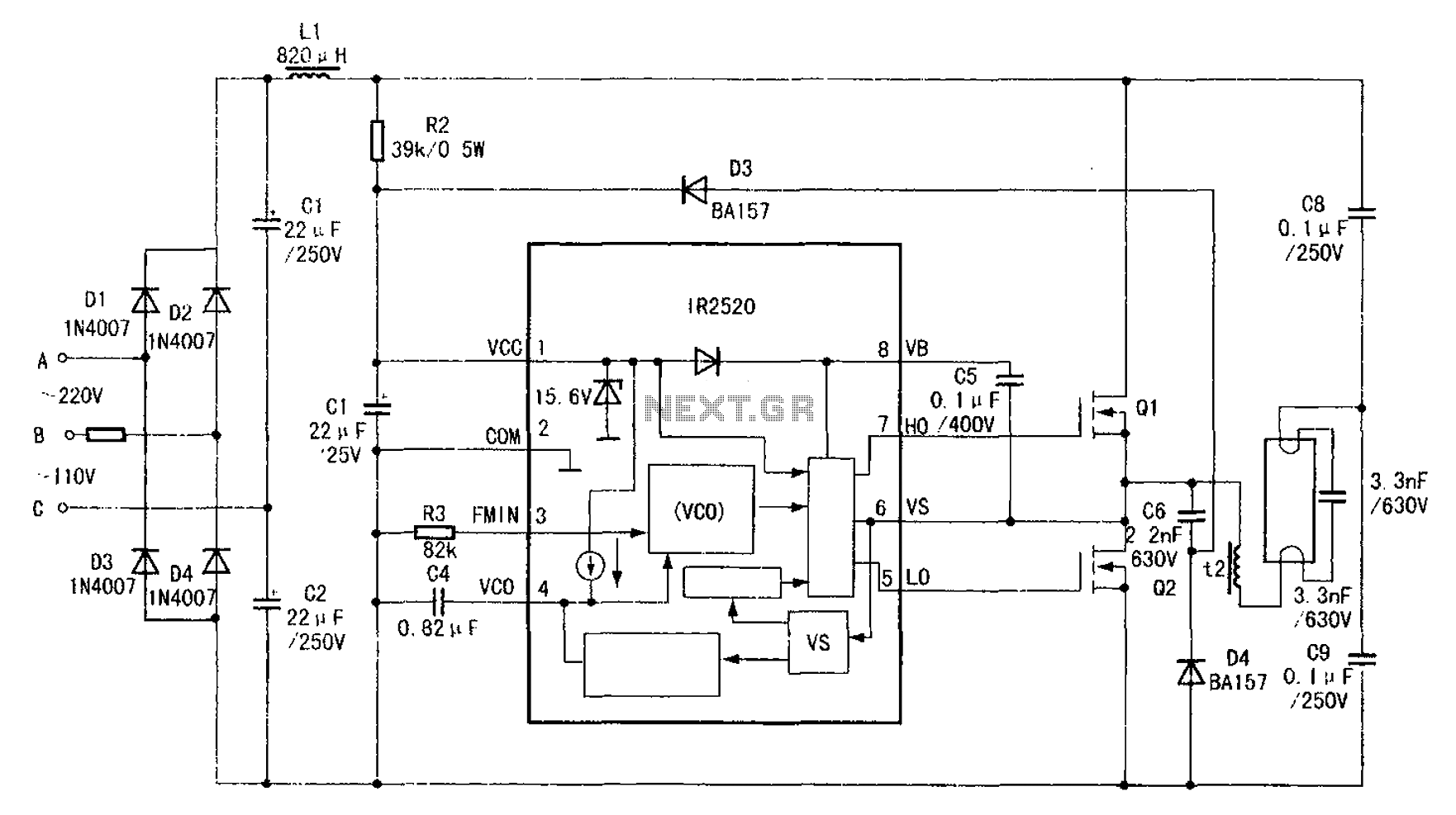
The adaptive zero voltage switching electronic ballast schematic diagram utilizes the IR2520 primarily for driving fluorescent lamps of 40W or less. The parameters of components such as Q1, Q2, L2, and C7 vary depending on the rated power of...
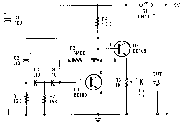
This circuit generates a sinusoidal output of approximately 8 V peak-to-peak, which can be adjusted down to zero, operating at a frequency of about 500 Hz. The signal is produced by a phase-shift oscillator. The described circuit utilizes a phase-shift...
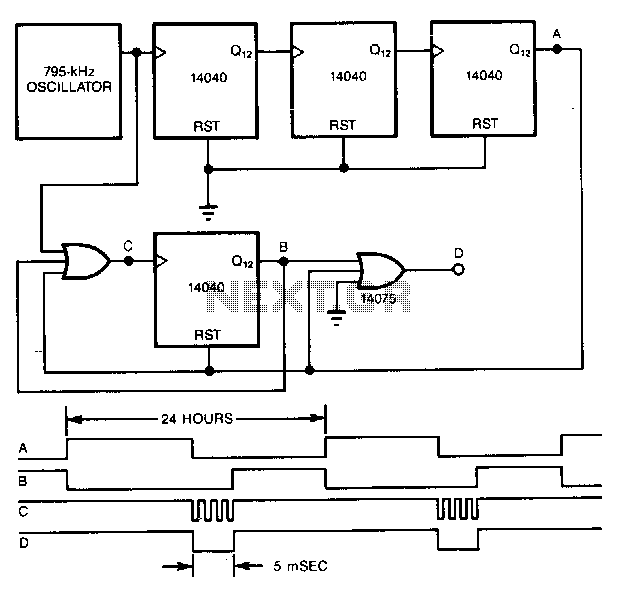
A precise pulse generator can be constructed using a precision oscillator and several CMOS counters. The number of counters can be increased to extend the pulse period as needed. This circuit will generate a pulse approximately 5 ms long...
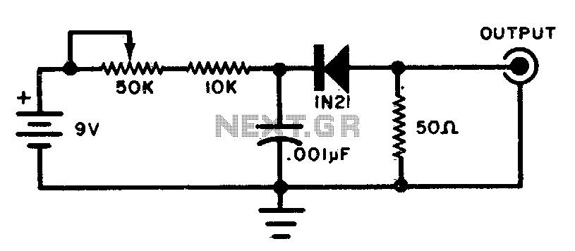
This circuit generates wideband RF noise utilizing a reverse-biased diode, featuring a low-impedance output. It can be employed to align receivers for optimal performance. The circuit primarily consists of a reverse-biased diode, which serves as the core component for generating...

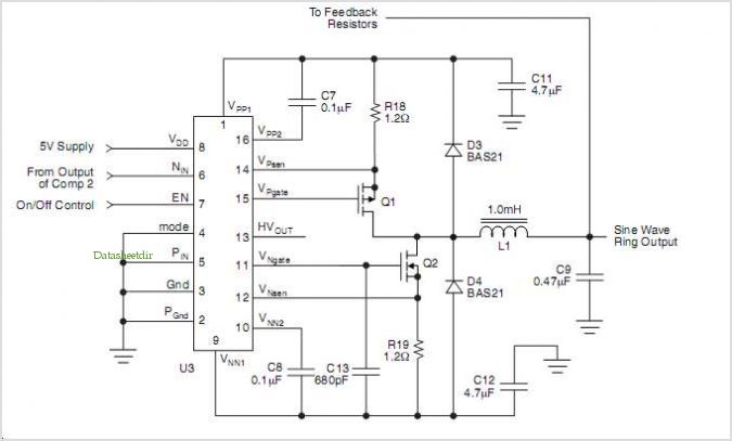
A simple yet effective circuit to generate a POTS-compatible ringing voltage can be constructed using National Semiconductor's LM4871 audio amplifier IC along with a dozen passive components. This circuit produces a sine-wave output of 1 W at approximately 70...